How Do You Minimize Losses in High-Power SMPS Magnetics?
Published by West Coast Magnetics, July 2026, based on our technical paper on designing high-power, high-frequency magnetics (available for download below); content reviewed and confirmed current as of publication.
In high-power SMPS magnetics, loss minimization drives the whole design because the magnetics can quickly become the largest, most expensive parts if done poorly. Four rules do most of the work: in transformers, minimize the number of winding layers and interleave the primary and secondary; treat transformers as loss/cost-limited (not saturation-limited) but inductors as usually saturation-limited; pick a higher-saturation core for inductors so the design can become loss-limited; and size to the worst-case RMS load over the component’s thermal time constant, not its instantaneous peak.
The goal in high-power switch-mode design is always loss minimization. You can remove heat from a component, but lower loss always advantages the design: smaller size, lower cost, better reliability. This article collects the practical rules; it pairs with choosing a core for a high-power SMPS transformer for core materials and sizing, and builds on the fundamentals in the SMPS transformer design guide.
Transformers: Minimize Layers and Interleave the Windings
AC winding loss in an SMPS transformer is driven by the winding magnetomotive force (mmf). Keep the mmf low and you keep the eddy-current-driven AC loss low. Two structural choices do that:
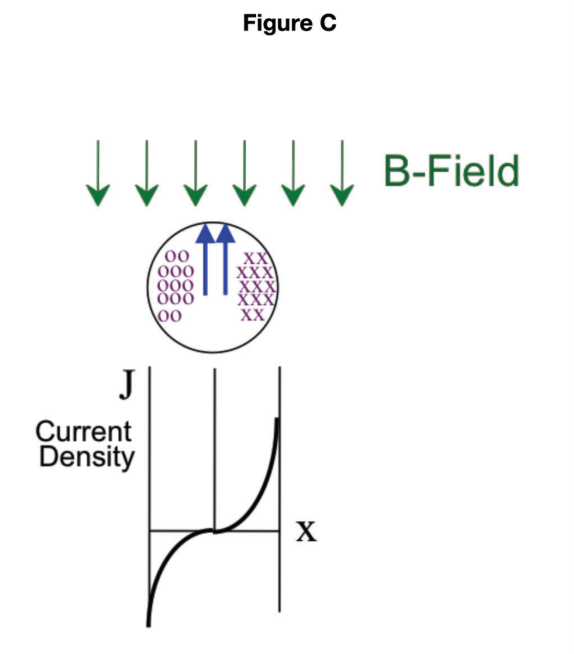
- Minimize the number of layers per winding. Each additional layer builds mmf across the winding stack, which raises AC copper resistance. Fewer layers means lower peak mmf and lower AC loss.
- Interleave or swap the primary and secondary. Splitting and alternating the primary and secondary sections resets the mmf profile within the winding window, cutting the peak mmf a solid block of one winding would otherwise see.
Both reduce AC loss without changing the turns or the core. How to choose the conductor itself (solid wire, litz, or foil) is covered in foil vs litz vs wire for SMPS windings.
Transformers Are Loss-Limited; Inductors Are Saturation-Limited
Core selection follows a different logic for the two component types, and getting this right changes which core you buy:
| SMPS transformer | SMPS inductor | |
|---|---|---|
| Usual limiting factor | Core loss and cost (not saturation) | Saturation flux density (Bsat) |
| Core-selection basis | Pick for low core loss and cost | Pick for adequate Bsat first |
| Design lever | Minimize layers, interleave windings | A higher-Bsat core can make the design loss-limited |
Because an SMPS transformer is typically not Bsat-limited, its core is chosen on core loss and cost alone. An inductor is usually saturation-limited, so choosing a core material with a higher saturation flux density can push the design from saturation-limited to loss-limited. When that happens you often get more inductance than you specified, and the extra inductance lowers ripple current, which in turn lowers AC winding loss. One good core choice pays off twice.
Size to the Thermal Time Constant, Not the Instantaneous Peak
Large transformers and inductors take 60 minutes or more to reach equilibrium temperature. That thermal inertia is a design tool: estimate the worst-case RMS load over a window close to that equilibrium time, not the momentary peak. If the component will never actually be fully loaded for an hour or more, there is no reason to size it for continuous full load. Magnetic components are robust and can handle high peak power and current for short periods, so designing to a realistic duty cycle over the thermal time constant avoids oversizing.
Why It Matters
High-power SMPS magnetics design is where a good or bad choice shows up fastest in size, cost, and thermal margin. These rules (low-mmf windings, the loss-vs-saturation core distinction, and duty-cycle-aware thermal sizing) are how a high-power transformer or inductor stays small and efficient instead of dominating the converter. They connect directly to what sets SMPS magnetics power density in the first place. WCM designs and builds these components in-house to the application’s real duty cycle and thermal envelope.
When standard components don’t fit your needs, our teams will engineer a solution.
FAQ
Keep the winding magnetomotive force (mmf) low. In practice that means minimizing the number of layers per winding and interleaving or swapping the primary and secondary sections. Both lower the peak mmf inside the winding window, which reduces the eddy-current-driven AC copper resistance without changing the turns count or the core.
An SMPS transformer is typically not saturation-limited, so its core is chosen on core loss and cost. An inductor is usually saturation-limited, so its core must first provide enough saturation flux density (Bsat). Choosing a higher-Bsat core for an inductor can move the design from saturation-limited to loss-limited, which is generally the better place to be.
If a higher-Bsat core makes the inductor loss-limited rather than saturation-limited, the design can end up with more inductance than specified. That extra inductance reduces ripple current, and lower ripple current directly lowers AC winding loss, so one core choice improves both the inductance and the losses.
Large transformers and inductors take 60 minutes or more to reach their equilibrium temperature, and they can handle high peak power for short periods. Estimating the worst-case RMS load over a window near that equilibrium time, rather than the instantaneous peak, prevents oversizing the component for a load it will never sustain long enough to overheat.
Because poorly designed magnetics quickly become the largest and most costly parts of a high-power converter. While heat can be removed, lower loss always helps: it shrinks the component, cuts cost, and improves thermal margin and reliability. That is why loss minimization, not just heat removal, drives high-power magnetics design.
 High-Power SMPS Magnetics Design Tips
 Contact Us