SMPS Transformer Design Guide: Core Selection, Isolation, and Thermal Design
Published by West Coast Magnetics, June 2026, based on our 2010 switch-mode transformer application note (available for download below); content reviewed and confirmed current as of publication.
An SMPS transformer is designed in a fixed order: choose the core and bobbin geometry, pick the mounting style and isolation class the application demands, select a core material, set the allowable temperature rise, then calculate primary turns from the volt-microsecond product. Geometry and isolation come first because they bound everything downstream: a surface-mount core cannot meet a 4000 Vac hypot, and a chassis-mount core is oversized for a 50 W rail. Switch-mode transformers operate at a duty-cycle-regulated frequency, typically between 10 kHz and 500 kHz, and the deliverable power for a given core scales with that frequency. Specify mounting style, isolation requirement, and operating frequency before you size the core, and the rest of the design loop stays short.
An SMPS transformer steps voltage or current up or down and provides isolation between the input and output of a switch-mode power supply. Unlike a line-frequency transformer, it is duty-cycle regulated: the on-time of the primary waveform is switched to hold the output constant under varying load. Because the gauss level is inversely proportional to the volt-microsecond product applied to the primary, raising the operating frequency lowers the required flux, which permits fewer turns and a smaller core for the same power.
This is the general SMPS transformer design guide. For the topology-specific case, see how to design a flyback converter transformer. Conductor selection (solid wire, litz, HV wire, and copper foil) is the other half of an SMPS transformer design and is covered in a separate guide; this article stays on core geometry, mounting, isolation, and thermal design.
How do you choose a core and bobbin geometry?
The first step in any SMPS transformer design is choosing a core and bobbin geometry. Most practical designs are derived from standard geometries offered by Ferroxcube and other manufacturers, so the real decision is which standard family fits the application. The deliverable power through a given core is a function of output power and frequency: as frequency increases, more power fits in a given core and bobbin, or a smaller core can carry the same power. The reason is that the gauss level is inversely proportional to the volt-microsecond product on the primary, so higher frequency means lower flux, fewer turns, and less core cross-section.
That scaling does not continue without limit. At higher frequencies, AC copper losses and volumetric core losses rise and begin to offset the benefit of lower flux, which is why power-versus-frequency curves flatten rather than climb indefinitely. For the high currents typical of low-voltage applications above 2.5 kW, managing AC winding losses becomes difficult, and scaling effects force lower power densities in both the core and the bobbin to hold the temperature rise down. As a result, higher-power SMPS designs typically operate at lower frequencies. Designs in the 500 kHz to 1 MHz range are common and successful, but they carry extra hurdles: AC copper loss becomes a dominant factor, winding parasitics and capacitive effects start to matter, and the best high-frequency cores are not always available through distribution.
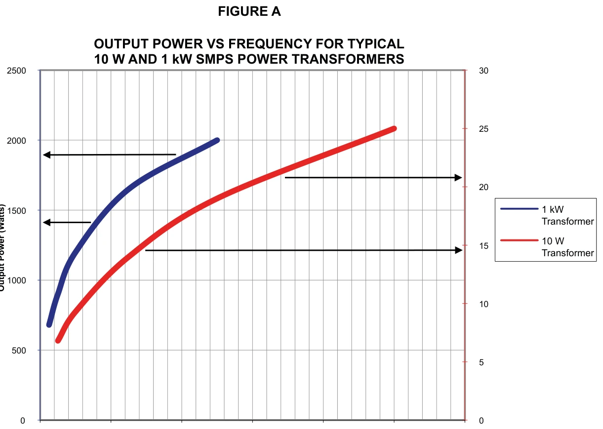
WCM publishes data sheets that give the power-handling capability of many cores as a function of frequency, based on a 40 degrees C rise for a conventional push-pull transformer with minimal parasitic losses. If the application demands high isolation, very high efficiency, or an input or output voltage above 200 V, expect to choose a larger size than the baseline curve suggests. WCM designs these as custom switch-mode transformers built to the specific converter requirement.
SMD, PCB, or chassis mount: which mounting style fits your application?
The mounting style is set by power, output voltage, frequency, and how much isolation the application requires. Each style maps to a different region of the design space, so picking the style early narrows the core search.
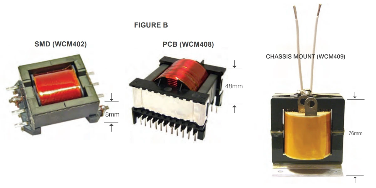
Surface-mount (SMD) cores and bobbins were originally developed for low-voltage applications. They are typically used at 100 kHz and up, at power levels up to about 250 W, with output voltage up to a practical limit of 750 V. The SMD window is low-profile with little clearance to the core, so creepage and clearance between input and output are typically limited to 4 mm, and hypot above 2500 Vac is difficult to achieve. SMD cores are therefore generally not suitable for isolation transformers that need safety-agency approval.
PCB-mount geometries offer far more choice. There are PCB-mount geometries that handle up to 2.5 kW, with output voltages up to 3000 V, and isolation up to 4000 Vac hypot with 10 mm creepage and clearance. Each geometry behaves differently, and some are far more suitable for isolation than others, so the specific core still has to be matched to the isolation target.
Chassis-mount transformers, such as the WCM409 (E 73, rated 5 kW), take over above 2.5 kW. They achieve very high isolation and accommodate output voltages up to 5000 V. With a chassis-mount design, the limit on high-voltage output is usually not the creepage and clearance built into a standard geometry but the capacitance of the high-voltage winding at SMPS frequencies.
| Mounting style | Power | Output voltage | Frequency | Safety isolation |
|---|---|---|---|---|
| SMD | ~1 W to 200 W | up to 750 V | 100 kHz to 1 MHz | Low voltage, low power only |
| PCB mount | ~1 W to 2500 W | up to 3000 V | 10 kHz to 500 kHz | Yes (up to 4000 Vac hypot, 10 mm) |
| Chassis mount | 1000 W and higher | up to 5000 V | 5 kHz to 500 kHz | Any |
Source: WCM SMPS transformer application note (appnote 11.28.10), Table 1.0.
How much isolation does the design need?
Isolation between input and output is determined by three independent factors: the creepage and clearance between windings, a dielectric (hypot) test in AC or DC, and the class of insulation between non-insulated conductors. These three are what a safety agency such as UL, CSA, VDE, or IEC evaluates. There is no trade-off among them: a higher-isolation design simultaneously demands greater creepage and clearance, a higher minimum dielectric test, and more robust insulation.
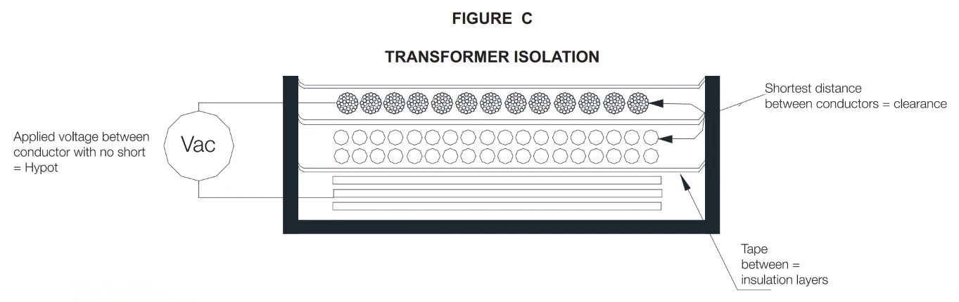
The amount of isolation required depends on the power level, the specific use of the transformer, and the voltage on each winding. The lowest level is operational isolation, where the only concern is minimal leakage current and no failures. A 5 W transformer stepping 12 V down to 3.3 V might need only a 250 Vac hypot to verify the interwinding insulation. At the other extreme, a transformer delivering power to a surgical application that requires patient isolation can face 10 mm minimum creepage and clearance, a 4000 Vac hypot, and reinforced insulation.
Temperature rise and operating frequency are independent of these three safety factors and are typically not part of an agency approval, provided the transformer’s temperature rise stays within the limits of the insulating materials. The practical consequence for sizing is this: when high isolation is required, derate the power a given geometry would otherwise support, because the winding window has to give up room to the added insulation and creepage and clearance. The table below shows how much that derating costs on a 1 kW PCB-mount core.
| Frequency | Operational isolation (W) | Safety-grade isolation (W) |
|---|---|---|
| 25 kHz | 680 | 410 |
| 50 kHz | 900 | 540 |
| 100 kHz | 1200 | 720 |
| 250 kHz | 1650 | 990 |
| 500 kHz | 2000 | 1200 |
Source: appnote 11.28.10, Table 2.0, WCM 408 ETD 54 (1 kW geometry). Safety-grade isolation runs roughly 60% of the operational rating on the same core.
When the application pushes isolation, creepage, and dielectric strength harder, WCM designs custom isolation transformers to the applicable agency standard.
What core material should you select?
SMPS transformers are loss-limited, not saturation-limited, so the material decision is driven by loss, not just by saturation flux. Almost all SMPS transformers use manganese-zinc (Mn-Zn) ferrite because it has the lowest losses at SMPS frequencies and is relatively low cost. Mn-Zn cores typically have a saturation flux density of 4000 to 5000 gauss, and SMPS designs are typically operated between 500 and 2500 gauss to keep core loss in check.
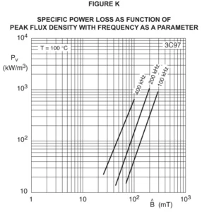
Within the Mn-Zn family there is real choice, and the materials are not interchangeable. Ferroxcube’s 3F45 has excellent loss characteristics above 500 kHz. Newer materials such as 3C95 and 3C97 are designed for lower losses across a much wider temperature range, which suits designs where efficiency matters across a broad operating band. Every successful design uses the manufacturer’s core-loss curve, which relates loss density to flux density and frequency, to estimate core losses under continuous operation. Two other material properties can matter in specific designs: core loss varies with temperature, and permeability varies with both temperature and peak flux density. For most SMPS transformers the permeability variation is not a concern, but it can be a factor in some designs. WCM engineers these as custom transformers, where the core, material, and winding are chosen together rather than from a catalog.
How do you size the thermal design and temperature rise?
Modern SMPS transformers have a very high power-to-size ratio, so they have to be efficient or they overheat. They can normally be designed to exceed 99% efficiency, though at that level there is usually a cost and sometimes a size penalty. Many designs are still built to a 40 degrees C temperature rise above ambient with no forced air. At a 40 degrees C rise the hot-spot temperature generally stays well within the limits of the materials of construction and the transformer runs at 95% efficiency or better. Forced air cooling, done correctly, lets the same transformer run at significantly higher loss (and lower efficiency) without overheating.
To size the thermal design without published surface-area data, use the coefficient of thermal resistivity, which is the temperature rise per unit of loss in degrees C per watt. Ferroxcube’s empirical study found that core volume is a reasonable proxy for this coefficient across many core and bobbin geometries, and core volume is published in every manufacturer’s data sheet. The curve fit is:
Rth = 53 x (Ve)^(-0.53), where Rth is the coefficient of thermal resistivity in degrees C per watt and Ve is the core volume in cubic centimeters.
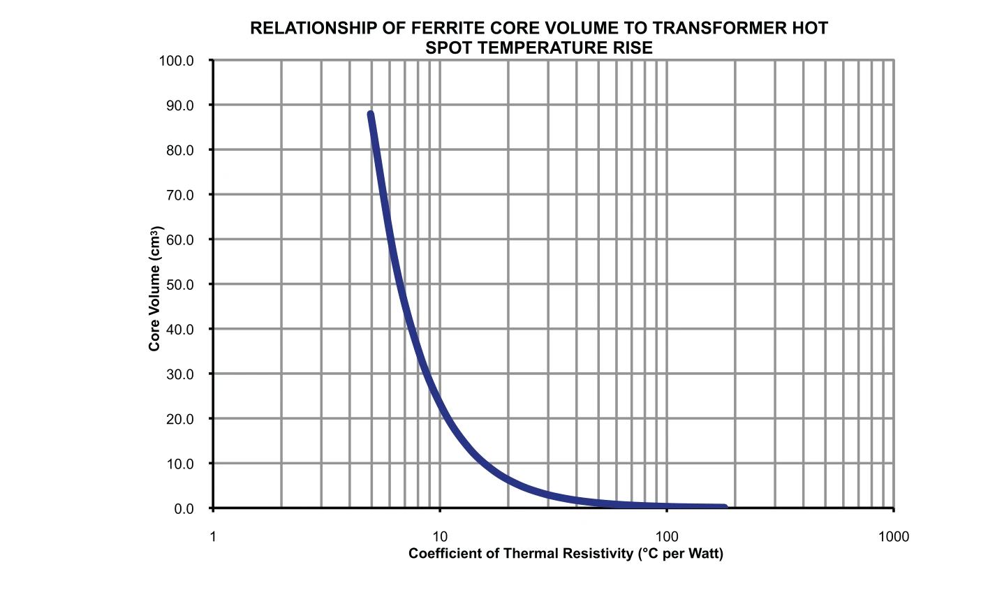
This is a first-order approximation. It sidesteps air-flow conditions, the rate of heat transfer to the surroundings at different ambient temperatures, and the varying ratio of surface area to core volume, but it is adequate as a first-level estimate for most SMPS designs. The thermal coefficient turns the design into a fast forward calculation rather than an iterative guess: pick an acceptable temperature rise, divide by Rth to get total allowable loss, budget roughly half of that as core loss, divide by core volume to get core-loss density in mW/cm^3, then read the gauss level off the manufacturer’s loss curve at the operating frequency. For a worked example, a WCM 402 EFD 30 core (Ve = 4.70 cm^3) gives Rth = 23.3 degrees C per watt; a 40 degrees C rise allows about 1.72 W of total loss, which budgets roughly 183 mW/cm^3 of core loss and points to about 1700 gauss at 100 kHz on 3C97 material.
How do you calculate primary turns?
Once the geometry and material are fixed, set the primary turns from the relation between flux density, the volt-microsecond product, and the core area:
B = (V x ton x 10^8) / (2 x Ae x N), where B is peak AC flux density in gauss, V is the primary voltage, ton is the primary switch on-time in seconds, Ae is the core area in cm^2, and N is the number of primary turns.
The design condition that usually produces the highest losses is minimum input voltage at maximum power under continuous duty, so that is the recommended first-pass case. Check the design at high input voltage as well, because depending on topology and the balance the designer strikes between core and copper loss, the high-line case can yield higher total losses. Continuing the worked example above, a 100 kHz design at 1700 gauss with a 70% maximum on-time, 85 V minimum input, and Ae = 0.69 cm^2 resolves to 25 primary turns. With the primary and secondary turns set, the remaining step is choosing a winding conductor for each winding (solid wire, litz, HV isolation wire, or foil), which is covered in SMPS transformer winding design.
Secondary turns follow from the topology’s input-output transfer function rather than a simple ratio, because an SMPS transformer is duty-cycle regulated. A common starting point is to divide Vout by Vin and add about 10%, which works well, but the exact transfer function gives a better turns ratio. Most topologies are duty-cycle limited to about 50% maximum on-time, though the forward converter and the flyback can exceed 50%. With multiple outputs, choose a topology that cross-regulates well and set each turns ratio carefully, since regulation applies to only one output. The flyback is the worked topology-specific example: see the flyback converter transformer design guide for that case.
When should you have WCM design the transformer?
There is a sound alternative to designing your own transformer: specify the core, bobbin geometry, and schematic, and WCM completes the design. WCM has completed hundreds of designs and delivers a specification sheet that certifies the key properties of the transformer you require. The same in-house design and test methods are documented across WCM’s custom magnetics capabilities. When standard components don’t fit your needs, our teams will engineer a solution.
FAQ
Work in order: choose the core and bobbin geometry, select the mounting style (SMD, PCB, or chassis) and isolation class the application requires, pick a core material (almost always a manganese-zinc ferrite), set an allowable temperature rise, then calculate primary turns from B = (V x ton x 10^8) / (2 x Ae x N). Geometry and isolation come first because they bound power, voltage, and frequency. Size for the worst case, which is usually minimum input voltage at maximum power under continuous duty, and verify the high-input-voltage case as well.
Use SMD for low-voltage, low-power designs up to about 250 W and 750 V at 100 kHz and above, where safety-agency isolation is not required (creepage and clearance are limited to about 4 mm and hypot above 2500 Vac is hard to reach). Use PCB mount up to 2.5 kW, up to 3000 V, with isolation to 4000 Vac hypot and 10 mm creepage and clearance. Use chassis mount above 2.5 kW, up to 5000 V, where very high isolation is needed.
Manganese-zinc (Mn-Zn) ferrite, because it has the lowest losses at SMPS frequencies and is relatively low cost. Mn-Zn cores have a saturation flux density of 4000 to 5000 gauss, and SMPS designs typically run between 500 and 2500 gauss. Within the family, materials differ: Ferroxcube 3F45 suits operation above 500 kHz, while 3C95 and 3C97 give lower losses across a wider temperature range. Always estimate core loss from the manufacturer’s loss curve for the specific material, since each one has a unique loss characteristic.
SMPS transformers are loss-limited, not saturation-limited, so the operating flux is set well below saturation. Manganese-zinc cores saturate at 4000 to 5000 gauss, but SMPS designs typically operate between 500 and 2500 gauss to keep core loss within the thermal budget. The exact level comes from the manufacturer’s core-loss curve at the operating frequency for the allowable core-loss density.
Use the coefficient of thermal resistivity, Rth = 53 x (Ve)^(-0.53), where Rth is in degrees C per watt and Ve is the core volume in cubic centimeters. Multiply allowable total loss by Rth, or divide the target temperature rise by Rth to get allowable loss. Many designs target a 40 degrees C rise above ambient with no forced air, which keeps the hot spot within material limits and yields 95% efficiency or better. This is a first-order approximation; confirm with measurement under actual load.
Isolation is set by three independent factors that a safety agency (UL, CSA, VDE, or IEC) evaluates: creepage and clearance between windings, a dielectric (hipot) test in AC or DC, and the insulation class between non-insulated conductors. They do not trade off against one another. Operational isolation can be as low as a 250 Vac hypot; a patient-isolation application can require 10 mm creepage and clearance, a 4000 Vac hypot, and reinforced insulation. When high isolation is required, derate the power the geometry would otherwise support to make room in the winding window.
 Contact Us