How Do You Choose the Windings and Conductors for an SMPS Transformer?
Published by West Coast Magnetics, June 2026, based on our 2010 switch-mode transformer application note (available for download below); content reviewed and confirmed current as of publication.
Once the core, bobbin, and turns count are set, the winding is what decides how much copper loss an SMPS transformer actually carries. The choice comes down to four conductor types (solid wire, litz wire, high-voltage isolation wire, and copper foil), and the right one for each winding depends on that winding’s current, operating frequency, voltage, and isolation requirement. This is the winding half of the design; for the core, geometry, material, and thermal budget that come first, see the SMPS transformer design guide.
Winding-conductor selection is the step in switch-mode transformer design where each winding is assigned a conductor type (solid wire, litz wire, HV isolation wire, or copper foil) to meet its current, frequency, and isolation needs at the lowest practical loss. AC copper loss is the frequency-dependent part of winding loss, driven by skin effect and proximity effect, that at switch-mode frequencies frequently exceeds the DC loss and can overwhelm a design if it is not managed.
How Are the Secondary Turns Determined?
Unlike a line-frequency transformer, an SMPS transformer is duty-cycle regulated, so the turns ratio is not simply the voltage ratio. It is set by the input-to-output transfer function for the chosen topology, which relates input voltage, output voltage, turns ratio, and the primary on-time together.
Many designers approximate the ratio by dividing the output voltage by the input voltage and adding about 10%, and that works reasonably well. Using the actual transfer function for the topology produces a better-informed and superior choice. Most topologies are limited to a 50% maximum duty cycle, though the forward converter and the flyback can run duty cycles above 50%. For a worked example of setting primary turns from the volt-microsecond product, and of the flyback converter transformer specifically, see those guides.
Regulation applies to only one secondary output. When a design has multiple outputs, two things matter: choose a topology that gives good cross-regulation between windings, and pick the turns ratio carefully so every output lands as close as possible to its target.
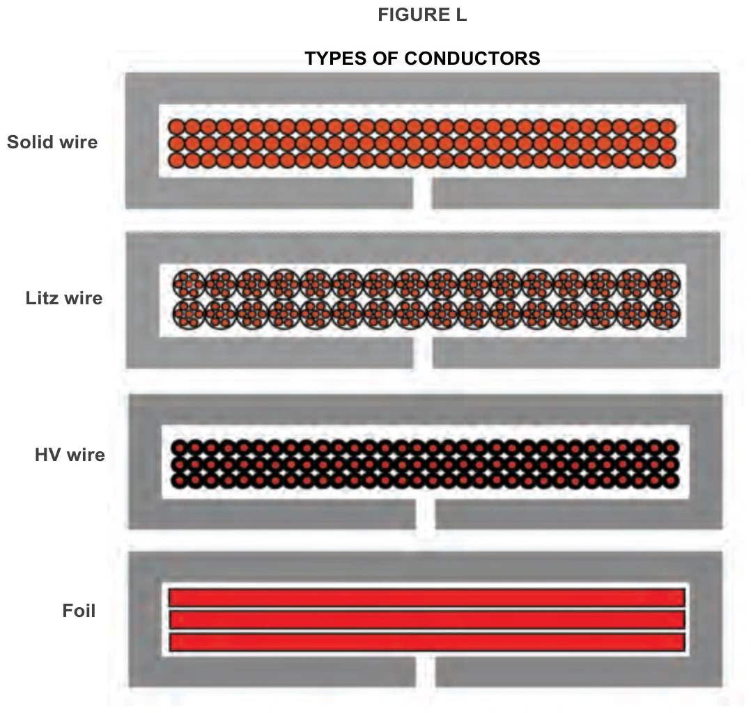
What Are the Four Winding-Conductor Types?
There are four basic classes of winding conductor, and the best choice depends on the specific requirements of each winding.
| Conductor | Best for | Key advantage | Main limitation |
|---|---|---|---|
| Solid wire | <= 100 kHz, under 20 A rms | Lowest cost in material and winding time | High AC resistance at SMPS frequencies; keep to one layer |
| Litz wire | Higher frequency, multilayer windings | Many fine strands cut AC resistance | Higher cost, lower window utilization, higher DCR than foil |
| HV isolation wire | Reinforced-insulation safety windings | Reaches 4000 Vac hypot with a modest diameter increase; simplifies the build | Higher cost and lower window utilization, like litz |
| Copper foil | Low-voltage, high-current windings | Highest window utilization and lowest DCR | Each turn is a layer, so capacitance and AC loss climb with turns |
Solid wire is typically used for transformers operating at 100 kHz and below and at RMS currents under 20 A. Its advantages are low material cost and low winding time. Its disadvantage is loss: solid wire can develop excessive AC winding resistance at SMPS frequencies, so a solid-wire winding should always be kept to a single layer where possible.
Litz wire is many fine, individually insulated strands twisted into one bundle. Strands are available from 24 AWG down to 50 AWG; at SMPS frequencies most designers use 36 to 44 AWG, with 36 to 40 AWG below 100 kHz and 42 to 44 AWG at higher frequencies. Dividing the conductor this way suppresses the eddy-current losses that drive AC resistance.
HV wire is a safety-isolation conductor with two or three thin layers of Teflon or a similar polymer (Tex-E and Rubadue are common). Its advantage is that it can reach a 4000 Vac hypot and a reinforced-insulation rating with only a modest increase in overall diameter, which vastly simplifies the build because no additional insulation, creepage, or clearance has to be engineered into the winding. Its disadvantages are the same as litz: higher cost and lower winding-window utilization.
Copper foil is an excellent choice for low-voltage windings. It typically gives far greater window utilization and the lowest DCR of any option, and it can be the lowest-loss choice. Its low-profile cross-section helps minimize copper loss, because the magnetic field in a transformer winding tends to draw AC current to the top and bottom of the winding. The disadvantage is that each turn is a single layer, so with many turns winding capacitance and AC copper loss add up quickly. For how WCM reshapes foil to cut that AC resistance in gapped inductors, see reducing winding losses in high-frequency inductors.
How Do You Estimate Winding Resistance and Loss?
Winding loss in an SMPS transformer has both an AC and a DC component. A useful first-order approximation of copper loss is to compute each winding’s DC resistance, multiply by that winding’s RMS current squared, and sum across windings. The DC resistance of a winding is its number of turns times the mean length per turn times the conductor’s resistance per unit length:
DCR = N x (mean length per turn) x (conductor resistance per unit length)
That captures the DC term. The AC term is harder. At switch-mode frequencies, AC losses frequently exceed DC copper losses and can overwhelm a design if they are not managed. Predicting AC copper loss precisely is complex, but the driver is skin depth. At 250 kHz, for example, the skin depth in copper is about 0.0148 cm, so a designer would need 35 AWG wire to keep the conductor within one skin depth. A single strand of 35 AWG carries very little current, which is exactly why litz wire is required in most higher-frequency designs.
A few rules of thumb keep AC copper loss under control:
- Minimize the number of layers in each winding. One layer is ideal, though not always possible.
- Interleave primaries and secondaries where the topology allows it.
- Keep a single-layer conductor’s diameter to one skin depth or less. Windings with more than one layer need even smaller conductors.
- Use litz or copper foil for any winding of two or more layers, or at 100 kHz and above.
For predicting litz copper loss specifically, the Thayer School of Engineering at Dartmouth maintains a free online tool, the same collaboration behind WCM’s shaped-foil work.
One more effect is easy to forget: copper resistance rises with temperature. It increases about 8% from 20 to 40 degrees C, 16% from 20 to 60 degrees C, and 24% from 20 to 80 degrees C, and that same percentage applies to both AC and DC copper loss. For temperature-rise-limited designs, calculate core and copper losses and the resulting temperature rise at the worst-case operating condition rather than at room temperature.
When Should You Let WCM Design the Winding?
Conductor selection, turns ratio, layer count, and interleaving all interact, and the AC-loss penalty for getting them wrong grows with frequency. WCM publishes data sheets that give the power-handling capability of many cores as a function of frequency, based on a 40 degrees C rise for a conventional push-pull transformer with minimal parasitic losses. If the application needs high isolation, very high efficiency, or an input or output voltage above 200 V, expect to size up from the baseline curve.
When the requirement is specific, WCM engineers these as custom switch-mode transformers, choosing the core, bobbin, turns, and winding conductor together rather than from a catalog, and delivering a specification sheet that certifies the key transformer properties.
FAQ
Match the conductor to the winding’s current, frequency, and isolation needs. Solid wire suits windings at 100 kHz and below and under 20 A rms, kept to a single layer. Litz wire (36 to 44 AWG strands) suits higher frequencies and multilayer windings. HV isolation wire suits reinforced-insulation safety windings. Copper foil suits low-voltage, high-current windings where its low DCR and high window utilization win, as long as the turn count stays low.
Use litz when the winding has two or more layers or operates at 100 kHz and above, because a solid conductor large enough to carry the current exceeds one skin depth and develops high AC resistance. At 250 kHz the copper skin depth is about 0.0148 cm, requiring roughly 35 AWG to stay within one skin depth, and a single 35 AWG strand carries too little current on its own. Litz divides the conductor into many fine strands to recover the lost area.
HV wire is a safety-isolation conductor with two or three thin polymer insulation layers (brands include Tex-E and Rubadue). It reaches a 4000 Vac hypot and a reinforced-insulation rating with only a modest diameter increase, which simplifies the build because no separate creepage, clearance, or insulation has to be added. The tradeoffs are higher cost and lower window utilization, similar to litz.
Copper foil gives the highest window utilization and the lowest DC resistance of the four options, and its low-profile cross-section minimizes AC copper loss because the winding’s magnetic field draws current to the top and bottom of the conductor. The limitation is that each turn forms a layer, so winding capacitance and AC loss grow quickly as the turn count rises, which makes foil best for low-voltage, low-turn-count windings.
For a first-order estimate, compute each winding’s DC resistance (turns times mean length per turn times the conductor’s resistance per unit length), multiply by that winding’s RMS current squared, and sum across windings. Then account for AC loss, which at switch-mode frequencies often exceeds the DC loss, by minimizing layers, interleaving primaries and secondaries, keeping single-layer conductors within one skin depth, and using litz or foil above 100 kHz. Add the copper-resistance rise with temperature (about 8% at 40 degrees C, 16% at 60 degrees C, 24% at 80 degrees C).
Because the transformer is duty-cycle regulated, the turns ratio comes from the input-to-output transfer function for the topology, not simply the voltage ratio. A quick approximation is output voltage divided by input voltage plus about 10%. With multiple outputs, choose a topology with good cross-regulation and set the turns ratio so each output lands as close as possible to its target, remembering that regulation applies to only one secondary output.
 Contact Us