How to Reduce Winding Losses in High-Frequency Inductors
Published by West Coast Magnetics, June 2026, based on our 2008 Power Electronics Technology article (available for download below); content reviewed and confirmed current as of publication.
The fastest way to lower winding losses in a high-frequency power inductor is to attack the AC component of winding resistance, not just the DC resistance. At switch-mode frequencies the AC component can be orders of magnitude larger than the DC resistance, and it is what actually drives copper losses. The four practical conductor choices (solid wire, litz wire, plain foil, and shaped foil) trade DC resistance against AC resistance differently. For high-current, high-ripple gapped inductors operating above 10% ripple and from 25 kHz to 500 kHz, West Coast Magnetics’ Shaped Foil Technology delivers the lowest total winding loss, pairing the low DC resistance of foil with litz-like AC resistance.
Shaped foil is a foil winding whose copper is reshaped near the core gap so the gap fringing flux equalizes current distribution across the foil, suppressing the skin and proximity effects that drive AC loss. Winding losses are the copper (I²R) losses in an inductor’s conductor, and they have two parts: a DC resistance term and an AC resistance term caused by skin effect and proximity effect that grows with frequency and current.
Why Winding Losses Spike at High Frequency
An inductor has two loss mechanisms: core losses (hysteresis and eddy currents in the core material) and winding losses (the copper). Winding resistance itself has two parts: a DC term and an AC term that comes from skin effect and proximity effect.
A time-varying current induces flux, which induces small eddy currents inside the conductor. Because very little current then flows through the center of the conductor, the effective cross-sectional area shrinks and resistance climbs. These losses grow as frequency and current rise. At switch-mode frequencies the AC component can greatly exceed the DC resistance, so AC copper loss dominates.
The gapped-inductor problem
Gapped power inductors make this worse. The field near the gap produces a strong local proximity effect, which can create very high AC copper resistance and loss, in extreme cases leading to inductor failure. This matters because many DC-DC converters need an inductor that carries a large DC current with an AC ripple, and even a small AC ripple can produce AC resistance orders of magnitude larger than the DC resistance.
A few standard mitigations help. Keeping windings to a single layer substantially reduces AC copper loss, and using an ungapped powdered core reduces proximity effects. But powdered cores typically have significantly higher core losses than ferrite, so for high-ripple work a gapped ferrite core is often preferred for its lower core loss. That leaves the gap fringing field as the problem to solve.
The Conductor Options and Their Tradeoffs
Solid wire has low DC resistance but medium-to-high AC resistance; at high frequency only the outer skin-depth shell carries current.
Litz wire divides the conductor into many fine strands, eliminating most eddy-current loss and reducing AC resistance, but it greatly increases DC resistance versus foil and is the highest-cost winding option.
Plain (full) foil uses the winding window efficiently and gives very low DC resistance, but each turn is a layer, so multi-turn foil has high AC resistance, and even a small amount of AC current causes significant loss.
In short, the common fixes force a tradeoff: litz cuts AC resistance but raises DC resistance, while foil cuts DC resistance but raises AC resistance. The engineering problem is to get both at once.
WCM Shaped Foil Technology
Shaped Foil Technology was developed by West Coast Magnetics with Dartmouth’s Thayer School of Engineering. The underlying method is patented by Dartmouth College, and WCM is a licensee. It shapes the foil in the vicinity of the core gap so the gap fringing flux is used to equalize current distribution across the foil, minimizing skin and proximity effects. The result is a single winding that pairs the very low DC resistance of foil with the low AC resistance of litz.
The experimental evidence
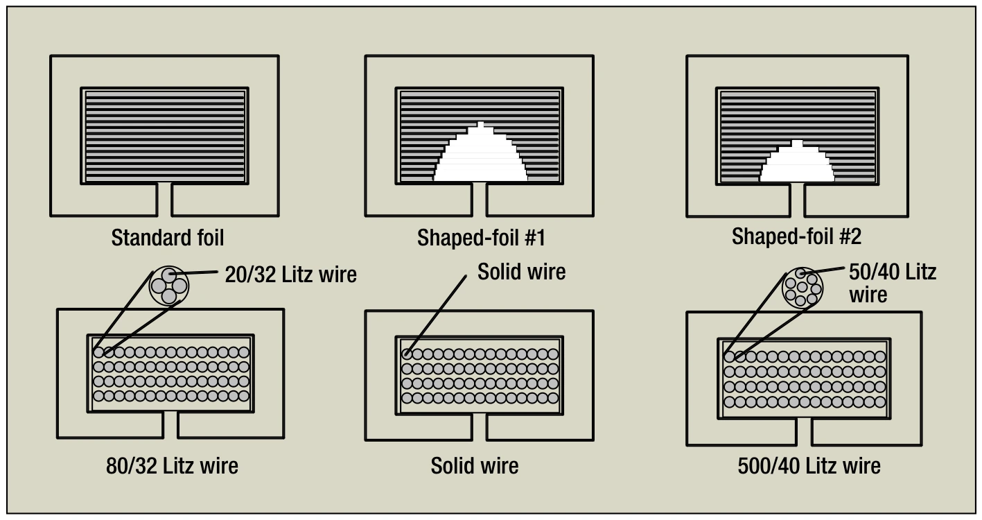
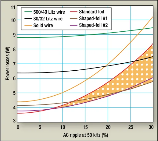
WCM and Dartmouth built a series of 90 µH, 40 A inductors, each on the same E70/33/32 EPCOS N67 ferrite core with a 2.63 mm center-leg gap and 15 turns, then compared solid wire, two litz constructions (500/40 AWG and 80/32 AWG), full foil, and two shaped-foil variants. Core losses were identical across all samples, so every measured difference came purely from the windings. Across ripple values from 1% to 30% and frequencies from 10 kHz to 500 kHz, shaped foil was the lowest-loss solution at ripple-current values above 10% and at frequencies from 25 kHz up to 500 kHz.
A later WCM/Dartmouth study extended the same idea with a foil-cut winding: copper removed near the gap rather than the foil edge reshaped. On a comparable gapped ferrite E-core, the modified 0.0243 in. cut design measured up to 68% lower winding loss than full foil at 100 kHz (at 30% ripple, 30 A DC), at a material cost well below litz. Because the cut copper is recovered close to its original value, the cost advantage holds in production.
Optimizing litz windings, too
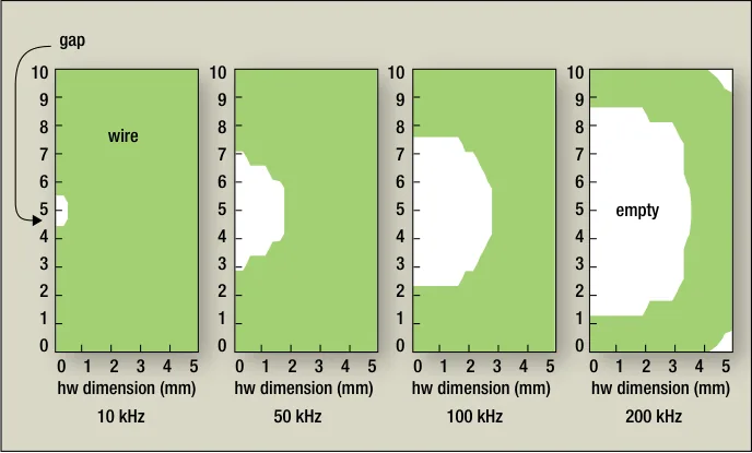
The same collaboration produced a litz-optimization path for designers who are committed to litz. Dartmouth’s Thayer School developed a freeware program, ShapeOpt, that optimizes litz strand count and the placement of the winding inside the bobbin window to minimize loss. The non-obvious finding: it is not optimal to fill the whole window with wire. Packing it solid produces much higher loss, and the penalty grows with frequency. In one worked example, with 0.05 mm (44 AWG) strands the program returned an optimal 314 total strands at 0.28 W of total winding loss. The result is practical to build: the region the optimizer leaves empty is masked off with a tape applied to the bobbin window, much like the margin tape used in standard winding, so the winder reproduces the optimized placement directly.
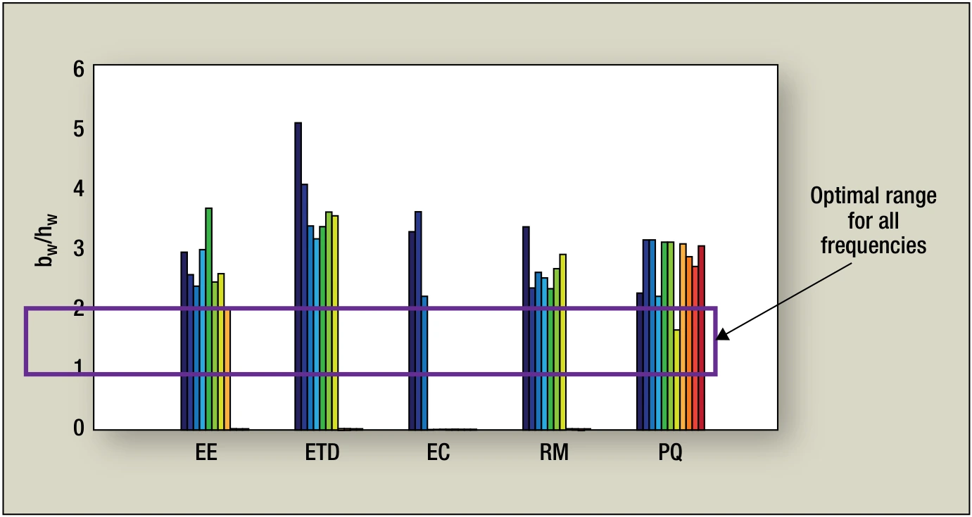
The study also surveyed core geometry. The optimal ratio of winding-window width to height rises from about 1 in the 1 kHz–10 kHz range to about 2 by 500 kHz, yet most stock E-core and bobbin geometries do not have window shapes well suited to gapped power inductors at high frequency. That gap between catalog cores and the optimum is one reason high-frequency power inductors so often need a custom inductor design rather than an off-the-shelf part.
Where it wins: shaped foil vs. toroids
Shaped foil is strongest in high-current, high-ripple gapped buck and boost inductors. In a boost-inductor benchmark on a gapped ferrite E-core (10 µH, 55 A rms, 65 A peak), the shaped-foil design ran far lower loss than two conventional powdered-core toroids built to the same requirement, at lower cost and smaller volume. Manganese-zinc ferrite has the lowest loss density of the common core materials, which is part of why the gapped-ferrite-plus-shaped-foil combination wins.
| Design (10 µH, 55 A rms, 65 A peak) | Loss at 100 kHz | Loss at 250 kHz | Cost per part (2022, 1,000-pc quote) |
|---|---|---|---|
| Shaped foil on gapped ferrite E-core | 5.45 W | 7.65 W | $4.69 |
| Iron-nickel toroid (7 AWG solid wire) | 10.35 W | 13.89 W | $16.18 |
| High-iron toroid (bifilar 10 AWG) | 14.19 W | 16.40 W | $9.48 |
Losses shown at 30% ripple current. Dollar figures are 2022 1,000-piece quotes and are not current pricing. Request a quote for your build. Note that the ferrite design’s inductance rolls off more quickly above its rated peak current than the powdered cores, so size to your limiting operating point.
WCM reports a significant price/performance gain over conventional windings for medium-to-high-power (1 kW to 110 kW) buck and boost inductors operating at peak-to-peak ripple of 10% or more of the DC current.
From the test bench to an orderable part
The benchmark parts above map directly onto WCM’s shaped-foil product families. For chassis-mount and surface-mount high-current designs, the WCM307 shaped-foil chassis power inductor and WCM308 shaped-foil SMD power inductor carry the technology in standard packages. For gapped buck/boost work in tighter envelopes, the compact WCM317 and WCM318 series, the WCM319 series, and the WCM320 power inductors cover a range of current and inductance points. When the constraint is a one-off (a specific inductance, current, ripple, and footprint), WCM’s custom power inductor team will engineer the winding and core to your spec, and our full design and test capabilities cover prototype through production. For high-Q and tuned high-frequency work outside the power-inductor range, see our custom resonant circuit inductors.
FAQ
Target the AC resistance, not just the DC resistance, because at switch-mode frequencies the AC component can greatly exceed the DC resistance. Keep the winding to a single layer where possible, choose the conductor type that fits your ripple and frequency, and for gapped high-ripple inductors use a winding that controls the gap fringing field, such as shaped foil.
Litz reduces AC resistance but raises DC resistance and is the most expensive option. Shaped foil keeps foil’s very low DC resistance while achieving litz-like AC resistance. In WCM/Dartmouth testing it was the lowest-loss option at ripple above 10% and frequencies from 25 kHz to 500 kHz, which is the operating window where it should be specified.
Plain foil gives excellent DC resistance and window utilization, but each turn forms a layer, so a multi-turn foil winding develops high AC resistance, and even a small AC current produces significant loss. Reshaping or cutting the foil near the gap is what corrects this.
Shaped foil wins for buck and boost inductors operating at peak-to-peak ripple of 10% or more of the DC current and at frequencies from roughly 25 kHz up to 500 kHz, across medium-to-high power levels (about 1 kW to 110 kW). Below 10% ripple or at very low frequency, the AC-resistance advantage shrinks and a simpler winding may be sufficient.
 Contact Us