What Is a Low AC Resistance Foil-Cut Inductor, and How Much Loss Does It Save?
Published by West Coast Magnetics, June 2026, based on our low-AC-resistance foil-cut inductor paper (available for download below); content reviewed and confirmed current as of publication.
A foil-cut inductor cuts AC winding resistance in a gapped power inductor without giving up foil’s low DC resistance. In testing by West Coast Magnetics and Dartmouth’s Thayer School of Engineering, the best foil-cut design measured up to 68% lower winding loss than full foil at 100 kHz (at 30% ripple, 30 A DC), and it did so at a material cost well below litz: $3,760 versus $19,933 for 1050/44 litz on a 1,000-part run. If you already know that shaped foil beats litz and solid wire on winding loss, this article is about the specific low-cost variant that gets there by removing copper near the gap, and the numbers that back it.
Foil-cut winding is a foil inductor winding in which copper is notched or cut away near the core gap so the gap fringing flux equalizes current distribution across the foil, suppressing the local proximity effect that drives AC resistance in a gapped inductor. It keeps the very low DC resistance of a full foil winding while cutting the AC resistance that full foil normally suffers.
For the general case of why shaped foil outperforms litz, solid wire, and plain foil on winding loss, see reducing winding losses in high-frequency inductors. This article stays on the foil-cut method and its measured loss and cost data.
Why Cut the Foil at All?
Full foil is attractive in a power inductor because it uses the winding window efficiently and gives very low DC resistance. The problem is AC resistance: in a gapped inductor the field near the gap drives a strong local proximity effect, and each foil turn is effectively a layer, so the AC resistance of a multi-turn foil winding climbs steeply with frequency. Even a small AC ripple current then produces significant loss.
Litz wire solves the AC-resistance side by dividing the conductor into many fine strands, but it raises DC resistance and is the most expensive winding option. The foil-cut method takes a different route: instead of switching conductor types, it reshapes the foil itself near the gap so the fringing flux equalizes the current across the foil. You keep foil’s DC resistance and recover most of the AC-resistance advantage that pushes engineers toward litz.
West Coast Magnetics developed this foil-cut technology in collaboration with the Thayer School of Engineering at Dartmouth, with guidance from Dr. Charles R. Sullivan on the cut-out geometry. The underlying shaped-foil approach is patented by Dartmouth College, and WCM is a licensee.
How the Foil-Cut Inductor Was Tested
To isolate the winding as the only variable, WCM and Dartmouth built nine windings on one fixed core and geometry: a Ferroxcube 3C90 E71/33/32 ferrite E-core with a 2.64 mm total center-leg gap (each half gapped 1.32 mm to keep the gap centered), 16 turns, and a 1.55 in. winding width on a rectangular bobbin. The target was a 110 µH inductor for operation up to 30 A DC with up to 35% AC ripple.
The nine windings were:
- 12 AWG solid magnet wire (wound trifilar, three layers, paralleled)
- 1050/44 served litz (trifilar) and 400/38 served litz (bifilar), both four layers
- Full foil in 0.0189 in. and 0.0243 in. thicknesses, 1.55 in. wide, with 0.003 in. Nomex between layers
- Four shaped foil-cut variants: 0.4 in. and 0.3 in. radius semicircle cut-outs centered on the air gap, plus a modified 0.4 in. cut
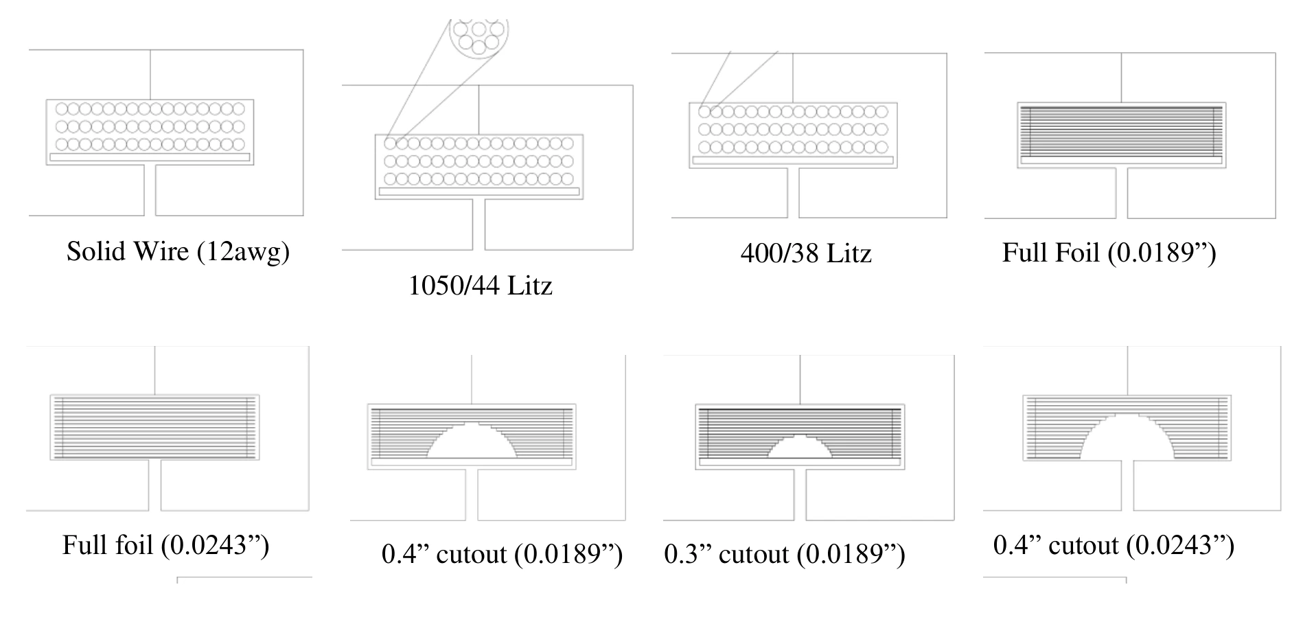
The “modified” 0.4 in. cut is the key design. It keeps the foil width across each layer constant while shaping the copper around the center gap and away from the corners, which reduces AC resistance while remaining practical to wind. DC resistance came from a current-source and voltmeter measurement; AC resistance was measured with an Agilent 4285A precision LCR meter from 75 kHz to 1 MHz and an HP/Agilent 4275A LCR meter from 10 kHz to 75 kHz.
How Much Winding Loss Does the Foil-Cut Method Save?
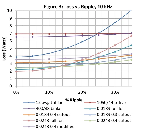
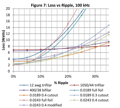
Comparing the 0.0243 in. modified 0.4 in. cut against the 0.0243 in. full foil baseline at 30% ripple and 30 A DC, the loss reduction grows with frequency: from 25% at 10 kHz to 68% at 100 kHz.
| Frequency | Full foil 0.0243 in. (loss, W) | Modified 0.4 in. cut 0.0243 in. (loss, W) | Reduction |
|---|---|---|---|
| 10 kHz | 5.43 | 4.07 | 25% |
| 20 kHz | 8.42 | 4.74 | 44% |
| 40 kHz | 15.82 | 6.50 | 59% |
| 80 kHz | 27.32 | 8.98 | 67% |
| 100 kHz | 31.70 | 10.14 | 68% |
Total winding loss at 30% ripple, 30 A DC, on the 110 µH test inductor. The reduction is the foil-cut design’s loss relative to same-thickness full foil.
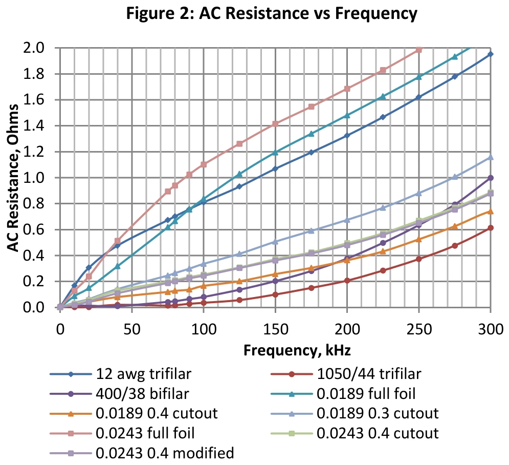
The reason the advantage widens with frequency is that the full foil’s AC resistance climbs steeply while the cut design’s stays comparatively flat. At 10 kHz and above, with medium-to-high ripple current, the foil-cut winding outperformed solid wire, litz, and full foil on overall winding loss. The cut design even beat the 400/38 bifilar litz, the strongest cost/performance litz in the set, by roughly 44%, 39%, 27%, 17%, and 16% at 10, 20, 40, 80, and 100 kHz.
Foil-Cut vs Litz: How Does the Cost Compare?
The cost case is what separates the foil-cut method from litz. On a production run of 1,000 parts, the 0.0243 in. modified 0.4 in. cut totals $3,760 in material cost, against $19,933 for 1050/44 litz and $10,101 for 400/38 litz.
| Winding (1,000-part run) | Total material cost |
|---|---|
| Modified 0.4 in. cut, 0.0243 in. foil | $3,760 |
| 400/38 litz (bifilar) | $10,101 |
| 1050/44 litz (trifilar) | $19,933 |
| 12 AWG solid wire | $5,630 |
| Full foil, 0.0243 in. | $6,260 |
Material cost for a 1,000-part run as quoted in the source paper. These are the source’s quoted run figures, not current WCM pricing; request a quote for your build.
Two things drive the cost advantage. Foil starts cheaper per pound than litz, and the copper removed in the cut is recovered close to its original value, so the net copper cost drops below even the full foil baseline. The result is a winding with both low DC resistance and low AC resistance at a material cost lower than litz, solid wire, and full foil.
That is the study’s bottom line: the foil-cut method is a less expensive way to reach higher efficiency than even 400/38 bifilar litz, the best cost-versus-performance litz in the comparison. You get the loss reduction that normally requires litz, but at a material cost below full foil, which is why it is a strong default for high-current, high-ripple gapped inductors.
Where the Foil-Cut Method Fits
The foil-cut winding is aimed at high-current, high-ripple gapped power inductors at 10 kHz and above. That is the same operating window where gapped ferrite cores are preferred for their low core loss but where full foil normally pays an AC-resistance penalty. It is well suited to buck and boost inductors in switch-mode converters; for boost-inductor core selection and design tradeoffs, see buck and boost inductors for SMPS converters.
If you are specifying a part rather than running a study, this technology lives in WCM’s shaped-foil product families, including the WCM307 shaped-foil chassis power inductor and the WCM308 shaped-foil SMD power inductor, and across WCM’s broader power inductor line. When the requirement is a specific inductance, current, ripple, and footprint that no standard part meets, WCM’s custom power inductor team will engineer the winding and core to your spec.
FAQ
It is a foil winding for a gapped power inductor in which copper is cut or notched away near the core gap. The cut lets the gap fringing flux equalize current distribution across the foil, which suppresses the local proximity effect that drives AC resistance. It keeps the low DC resistance of full foil while cutting the AC resistance full foil normally suffers.
In WCM and Dartmouth testing of a 110 µH inductor at 30% ripple and 30 A DC, the modified 0.4 in. cut in 0.0243 in. foil measured 25%, 44%, 59%, 67%, and 68% lower winding loss than the same-thickness full foil at 10, 20, 40, 80, and 100 kHz. The advantage widens with frequency because full foil’s AC resistance climbs steeply while the cut design’s stays comparatively flat.
Yes, by a wide margin in the tested case. On a 1,000-part run, the modified 0.4 in. cut totaled $3,760 in material cost versus $19,933 for 1050/44 litz and $10,101 for 400/38 litz. Foil is cheaper per pound than litz, and the copper removed in the cut is recovered close to its original value. These are the source paper’s quoted run figures, not current pricing.
At 10 kHz and above with medium-to-high ripple current, the foil-cut winding outperformed solid wire, litz, and full foil on overall winding loss in the tested design. Below that, the AC-resistance advantage shrinks and a simpler winding may be sufficient.
The cut removes some copper, so the DC resistance of a cut design is modestly higher than the matching full foil (for example, 3.90 mOhm for the modified 0.0243 in. cut versus 2.16 mOhm for the 0.0243 in. full foil). The net winding loss is still far lower because the AC-resistance reduction dominates at the frequencies and ripple levels where the part is used.
Both reshape the foil near the gap to use the fringing flux to equalize current. Shaped foil reshapes the foil edge or profile; the foil-cut variant removes copper near the gap, and the removed copper is recovered to lower cost. For the general shaped-foil-versus-litz background, see the winding-loss article.
 Contact Us