How to Design a Flyback Converter Transformer
Published by West Coast Magnetics, June 2026, based on our flyback converter design application note (available for download below); content reviewed and confirmed current as of publication.
A flyback converter transformer is designed by working backward from four inputs: the minimum and maximum input voltage, the output load, the maximum PWM duty cycle, and the allowable temperature rise. From those you set the primary inductance (which fixes discontinuous versus continuous operation), the turns ratio, the core geometry and material, the air gap, and the winding pattern. Most flyback designs run in discontinuous mode because the transformer is smaller and the supply is more stable, and the flyback works well for low-power isolated designs below about 200 W with DC isolation up to 5000 V. The two design choices that drive everything else are the primary inductance and the core, so specify the full input list before you start to keep the design loop short.
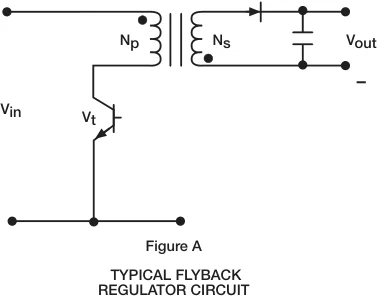
A flyback transformer is the energy-storage transformer in a flyback converter. It stores energy in its core during the switch on-time and releases it to the secondary during the off-time, so it acts as two coupled inductors that never conduct at the same instant. This is why the primary inductance, not just the turns ratio, sets the converter’s behavior.
What is the flyback topology, and when should you use it?
The flyback is one of the most widely used topologies for low-power (< 200 W) switch-mode supplies. It provides DC isolation of up to 5000 V, needs only one switching device, requires no output inductor, and is more failure-tolerant than a non-isolated topology. Adding multiple outputs (positive or negative) on a single transformer is straightforward, and the input voltage range is typically 3:1, with special designs accommodating ratios as high as 6:1. The core advantages are simplicity and cost.
The tradeoffs steer you to another topology when output quality matters most. Input and output current ripple is high, cross regulation is typically around +/-5%, and the high ripple currents make the flyback less efficient, which is why it is generally not used for high-power applications. The flyback can also produce large voltage spikes on the primary that stress other components, so the design and build process must be controlled carefully. You can address ripple and cross regulation by adding components, but that erodes the simplicity and cost advantage that justified the flyback in the first place. WCM designs these as custom switch-mode transformers built to the specific converter requirement; the broader SMPS transformer design guide covers core, mounting, isolation, and thermal selection across topologies.
DCM vs CCM: which operating mode should the transformer support?
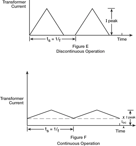
The primary inductance sets the operating mode. In discontinuous conduction mode (DCM) the secondary current falls to zero before the switch turns on again, leaving a short dead time each cycle when nothing in the transformer is energized. That dead time is unique to the flyback and is what lets it regulate over wide input-voltage and output-current ranges. In continuous conduction mode (CCM) the output current never reaches zero, so the ripple rides on a DC pedestal that creates a strong DC bias in the core.
Most flyback designs are discontinuous because the transformer is smaller and the supply is more stable. You can deliver more power to the load (and shrink the transformer further) by reducing the primary inductance, but reliability sets the floor: higher peak currents stress the power semiconductors and can cause them to fail. CCM trades those high peak currents for lower peak currents, which improves reliability and reduces switching losses and improves efficiency, at the cost of a harder control problem. Note that a design intended for DCM can revert to CCM when the input voltage drops too low.
| Parameter | Discontinuous (DCM) | Continuous (CCM) |
|---|---|---|
| Output current each cycle | Falls to zero, with a dead time | Never reaches zero (rides on a DC pedestal) |
| Primary inductance | Lower | Higher |
| Transformer size | Smaller | Larger |
| Peak currents | Higher | Lower |
| Efficiency / switching loss | Lower efficiency, higher peak stress | Higher efficiency, lower switching loss |
| Core DC bias | Minimal | Strong DC bias to design around |
| Control | Stable, regulates over wide range | Right-half-plane zero requires compensation |
| Typical use | Most flyback designs | When efficiency and reliability are driving concerns |
Source: WCM application note ALNT 1440. DCM is the default; CCM is chosen when efficiency and reliability dominate.
The CCM control problem is specific and worth calling out. Continuous-mode operation introduces a negative zero in the small-signal control-to-output transfer function located in the right half of the frequency plane. It rarely causes converter failure, but it does degrade stability and transient response, so a continuous-mode design needs compensation. This is typically handled by adding current-mode control to the topology.
How do you select the core geometry and material?
Several core geometries suit flyback transformers: pot cores, E cores, EP cores, and RM cores. WCM’s 401, 402, 403, 404, 405, 406, and 407 series cores are well suited to flyback applications. The size you choose is a function of operating frequency, throughput power, allowable losses (expressed as temperature rise), and safety-agency requirements.
Flyback transformers are typically built from high-quality power ferrite, and you select permeability by operating frequency: for operation below 500 kHz, most designers use a material with a permeability of 2000 to 2500. Permeability shifts with temperature and operating flux density, but this does not change converter operation as long as the core stays away from saturation, because the inductance that sets the operating mode is determined primarily by the air gap. Temperature rise and operating flux density do affect core losses, so account for them to ensure reliable operation. Do not substitute one ferrite for another merely because the permeability matches: every power material has a unique loss curve, and you should estimate core losses from the manufacturer’s curves for the exact material used.
WCM designs around the air gap to control mode and DC bias. The gap follows from the number of primary turns and the inductance specification, and it must be large enough to prevent saturation from DC bias. A typical primary inductance specification for a flyback transformer might be on the order of 50 microhenries +/-10%, determined at high output current and low input voltage because that is the most severe loading condition. WCM engineers these as custom transformers, where the core, gap, and winding are chosen together rather than from a catalog.
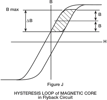
What flux-density and thermal limits apply?
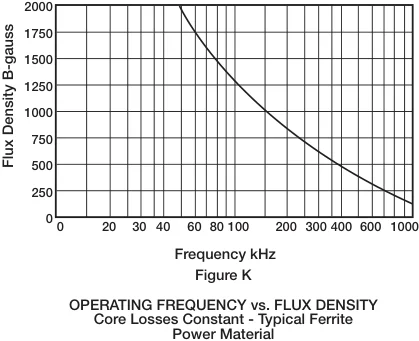
Flyback transformers operate in the first quadrant of the hysteresis loop. Peak operating flux density is typically limited to 2000 gauss at 50 kHz, though this varies with geometry: smaller cores can dissipate more power per unit volume. As operating frequency increases, lower flux levels are required to hold core losses constant, so the usable flux density falls as you move up in frequency.
Temperature rise comes from two sources: core losses and copper losses. Core losses are set by core geometry, material, operating frequency, turns, and primary voltage, which together fix the operating flux density and therefore the loss density (typically expressed in mW/cm^3). Copper losses include DC losses plus AC losses from eddy currents at the conductor surface (skin effect) and from proximity effects of adjacent windings. As frequency rises, AC losses force finer-gauge wire or copper foil, which reduces the copper area per unit of bobbin window. Final loss calculations must include AC and DC resistance and the temperature rise of the wire, since higher temperature raises copper resistivity. WCM applies the same low-AC-loss winding methods it uses across its custom magnetics design and test capabilities.
WCM typically uses Class B (130 degrees C) materials. A good thermal rule of thumb is to allow for a 40 degrees C operating temperature rise at maximum load, which in most cases keeps the part safely below the 130 degrees C material rating given ambient conditions. Measured temperature rise can range from as low as 10 degrees C to as high as 60 degrees C depending on the application. Theoretical temperature-rise calculations are not a substitute for thermocouple measurements under actual load in the real circuit, and thermocouple measurements are recommended in all cases, especially when safety-agency approval is required.
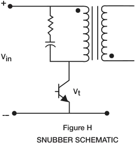
How do you control voltage spikes and leakage inductance?
The coupling between the primary and secondary windings, and between the windings and the core, sets the magnitude of the voltage spikes across the switching transistor. A large spike can destroy the PWM. You can add a snubber across the primary to clamp the spike, but it adds cost and complexity and significantly reduces efficiency. In most cases a snubber can be avoided by careful winding design and controlled manufacturing.
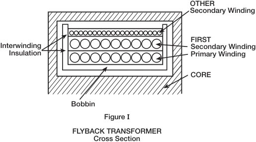
You control coupling by controlling leakage inductance and interwinding capacitance, both of which are measurable. Effective techniques include multistranded layered windings, copper foil windings, and bifilar windings, and the order in which the windings are placed on the bobbin matters. In production this is held in tolerance through automated winding and testing equipment.
What isolation and safety requirements drive the design?
Flyback converters often carry special build and test requirements to meet safety agencies, which is why isolation is a first-class design input rather than an afterthought. These requirements can include any of the following:
- Hipot: applied VAC or VDC between selected windings and between the core and selected windings.
- Creepage and clearance: the distance between uninsulated portions of selected windings, and between the core and uninsulated windings, measured per UL or IEC guidelines.
- Insulation system: a UL-recognized transformer rated Class B (130 degrees C) or higher generally requires a UL-approved insulation system.
- Insulating materials: UL and IEC specifications often dictate the thickness and number of insulation layers required between selected windings.
Because the flyback already provides DC isolation up to 5000 V, it is a natural fit for medically and industrially isolated rails. For builds that push isolation and creepage harder, WCM also designs custom isolation transformers to the applicable agency standard.
FAQ
Start by specifying the design inputs: minimum and maximum input voltage, output load (voltage and current per output), output diode drops, maximum PWM duty cycle, switching-transistor voltage drop, and target efficiency or allowable temperature rise. Express the efficiency target as a loss budget in watts, because that budget is what sizes the core and sets the allowable temperature rise. The output diode’s forward drop is the primary factor affecting load regulation (and its losses feed the loss budget), so specify it carefully along with the diode for each output. From those, set the primary inductance (which determines discontinuous versus continuous operation), the primary-to-secondary turns ratio, the core geometry and ferrite material, the air gap, and the winding pattern. Determine inductance at high output current and low input voltage, the most severe loading condition.
Most flyback designs run in discontinuous mode (DCM) because the transformer is smaller and the supply is more stable. Choose continuous mode (CCM) when efficiency and reliability are driving concerns, since it has lower peak currents and lower switching losses. The cost of CCM is a control problem: it introduces a right-half-plane zero in the control-to-output transfer function, which requires compensation, typically current-mode control.
Peak operating flux density is typically limited to about 2000 gauss at 50 kHz, because the flyback operates in the first quadrant of the hysteresis loop. Smaller cores can run somewhat higher because they dissipate more power per unit volume. As operating frequency increases, you must use lower flux levels to keep core losses constant.
Use a high-quality power ferrite, selecting permeability by frequency. For operation below 500 kHz, most designers use a permeability of 2000 to 2500. Do not swap one ferrite for another just because the permeability matches: estimate core losses from the manufacturer’s loss curves for the specific material, since every power ferrite has a unique loss characteristic.
The maximum duty cycle for a flyback PWM is typically 45% to 50%. At high input voltage the switch on-time becomes very short, which can reduce efficiency and, in fixed-frequency current-mode designs, lead to a runaway failure mode, so the maximum input voltage and the duty-cycle limit must be specified carefully.
A flyback provides DC isolation up to 5000 V. Safety-agency requirements can add hipot testing (applied VAC or VDC between windings and between core and windings), creepage and clearance distances per UL or IEC, a UL-approved insulation system for Class B (130 degrees C) and higher ratings, and specified insulation thickness and layer counts between windings.
 Contact Us