What Are Skin Effect and Proximity Effect in Magnetic Windings?
Published by West Coast Magnetics, July 2026, based on our presentation on optimal winding design for SMPS inductors (available for download below); content reviewed and confirmed current as of publication.
Skin effect and proximity effect are the two mechanisms that make a winding’s AC resistance higher than its DC resistance at switch-mode frequencies. Skin effect is a conductor pushing its own high-frequency current toward its surface; proximity effect is an external magnetic field (from nearby turns or a gapped core) forcing current to redistribute within the conductor. Both crowd the current into a fraction of the copper, and both are why the winding you choose matters as much as the turns you wind.
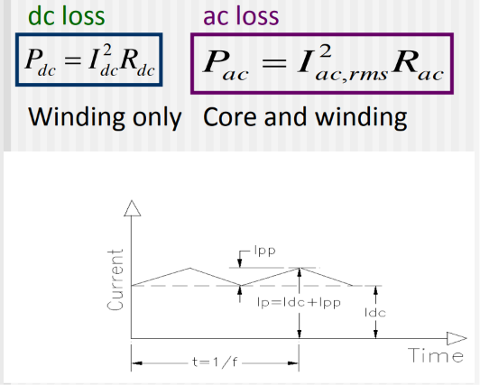
An inductor’s winding loss has two parts: a DC loss set by the DC resistance (I²·R_dc), and an AC loss set by the AC resistance and the ripple current (I²_ac,rms·R_ac). The DC part is just the copper you use. The AC part is governed by skin and proximity effects, and at SMPS frequencies (10 kHz and up) it can rival or exceed the DC loss. Understanding these two effects is the foundation for choosing a winding conductor and for litz-wire design.
Skin Effect: A Conductor Crowds Its Own Current to the Surface
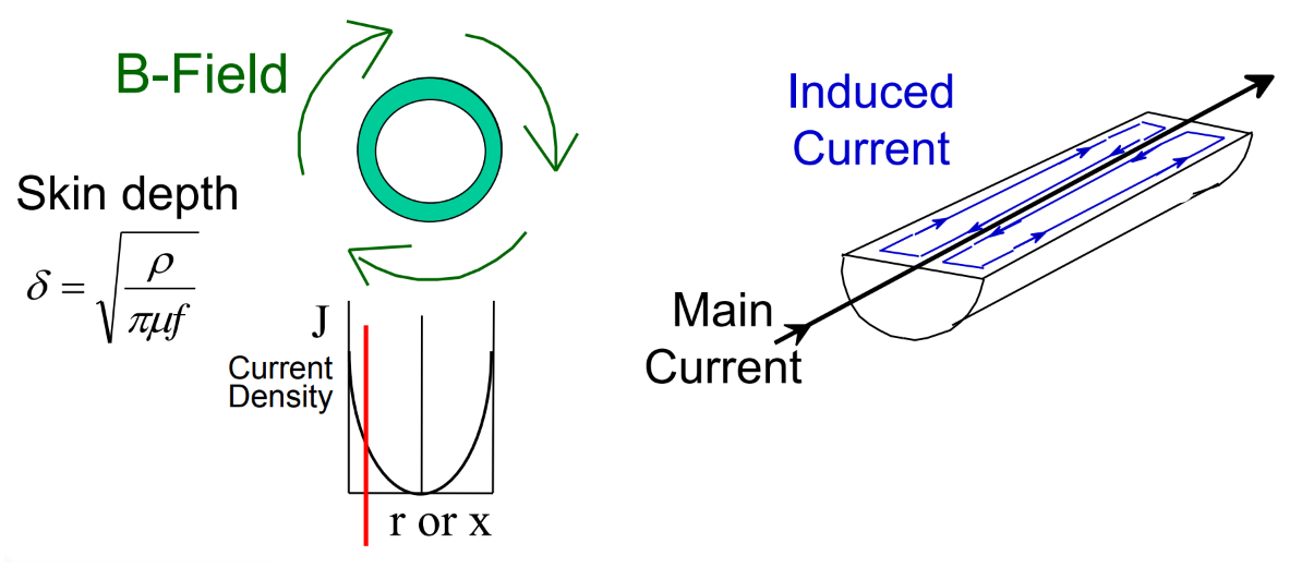
A conductor carrying high-frequency current generates a magnetic field in itself that forces that current to flow near the surface. The deeper you go into the conductor, the less current there is.
Skin depth is the distance below the surface of a thick plane conductor at which the field magnitude and current density fall to 1/e (about 37%) of their surface values. It shrinks as frequency rises.
The practical consequence: above some frequency, the center of a solid conductor carries almost no current, so the effective (usable) copper cross-section is far smaller than the physical one. Making the wire fatter doesn’t help much, because the skin depth is set by frequency, not by conductor size, so the extra copper just sits idle in the middle.
Proximity Effect: An External Field Redistributes the Current
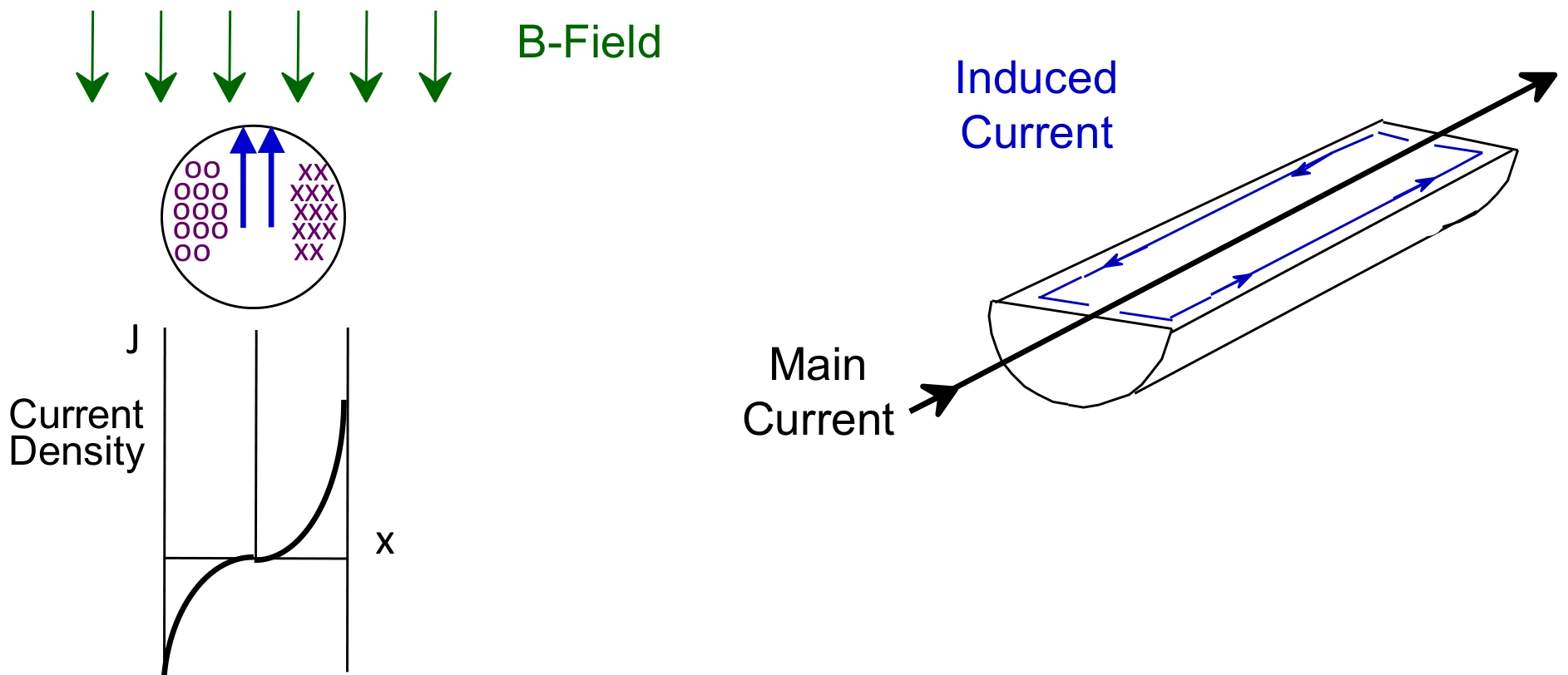
Proximity effect appears when a conductor sits in a magnetic field produced by something other than its own current: neighboring wires, adjacent winding layers, or the fringing field around the gap in a gapped core. That external field induces currents in the conductor that add to and subtract from the main current, pushing the net current into part of the conductor and away from the rest.
In a multi-layer winding the field builds layer by layer, so proximity effect often dominates the AC loss in a stacked winding. Near a core gap, the concentrated fringing field can pull the current into a small region of the copper closest to the gap. Both cases waste copper cross-section the same way skin effect does, just driven by an outside field instead of the conductor’s own.
How Conductor Choice Responds
Because AC resistance is where skin and proximity losses show up, the conductor form is a direct lever on it. The three common options trade DC resistance against AC resistance:
| Winding conductor | DC resistance (DCR) | AC resistance (ACR) |
|---|---|---|
| Copper foil | Very low | Medium |
| Solid round wire | Low | High |
| Litz wire (fine strands) | Medium to high | Low |
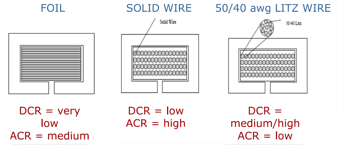
Foil packs the window efficiently for a very low DCR, but a foil layer has a medium ACR because the field drives current to its edges. Solid round wire keeps a low DCR but has the highest ACR of the three, because round conductors in a multilayer stack suffer strong proximity losses. Litz wire divides the conductor into many fine, individually insulated strands so that each strand is thinner than a skin depth, which keeps the AC resistance low; the tradeoffs are a higher DC resistance (the strand insulation and inter-strand voids reduce the copper fill) and higher cost. Which one wins depends on how much ripple current the winding carries and at what frequency, which is exactly the tradeoff covered in foil vs litz vs wire.
Why It Matters
Skin and proximity effects are why a winding that looks fine on DC resistance can run hot in a real converter: the ripple current sees the AC resistance, not the DC value. Getting the winding right (the conductor, the number of layers, the placement relative to the gap) is how WCM keeps winding losses low in high-frequency inductors. It is also the physics that WCM’s shaped-foil work was built to exploit, using the gap field deliberately rather than fighting it.
When standard components don’t fit your needs, our teams will engineer a solution.
FAQ
Skin effect is the tendency of high-frequency current in a conductor to flow near the conductor’s surface. The current generates a field in the conductor that forces itself outward, so the center carries little current. Skin depth, the distance at which current density falls to about 37% (1/e) of the surface value, shrinks with frequency, which is why a solid conductor’s usable copper cross-section drops as frequency rises.
Proximity effect is current redistribution caused by an external magnetic field (from neighboring turns, adjacent layers, or a gapped core’s fringing field) rather than by the conductor’s own current. Skin effect is self-induced; proximity effect is induced by nearby fields. In multi-layer windings proximity effect often dominates the AC loss, and near a core gap it can crowd current into a small part of the copper.
Because the ripple current flows through the AC resistance, not the DC resistance. At switch-mode frequencies of 10 kHz and up, skin and proximity effects can make the AC resistance equal to or greater than the DC resistance, so AC loss (ripple current squared times AC resistance) can rival or exceed the DC loss. A winding chosen only on DC resistance can therefore run much hotter than expected.
Because skin depth is set by frequency, not by conductor size. Above the relevant frequency the current still only flows within roughly one skin depth of the surface, so a thicker solid wire just adds copper in the center that carries almost no current. The fix is to divide the conductor (litz wire) or reshape it, not to enlarge it.
Litz wire splits the conductor into many fine, individually insulated strands, each thinner than a skin depth, and transposes them so each strand spends equal time in every position. That keeps skin and proximity effects small, giving low AC resistance, at the cost of a somewhat higher DC resistance than a solid conductor of the same window (strand insulation and voids reduce the copper fill) and higher material cost, which rises steeply as the strand gauge gets finer.
 Skin Effect and Proximity Effect in Windings
 Contact Us