Which Winding Should You Use in an SMPS Inductor? Foil, Litz, or Solid Wire
Published by West Coast Magnetics, July 2026, based on our 2018 APEC presentation on foil windings for SMPS inductors and transformers (available for download below); content reviewed and confirmed current as of publication.
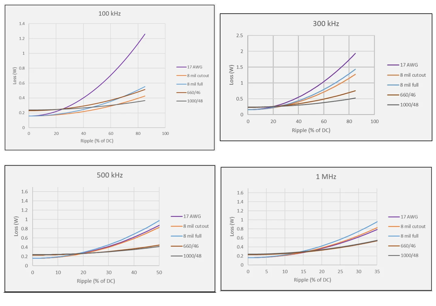
The lowest-loss winding for a gapped SMPS inductor is set by the ripple-frequency product: the percent ripple current multiplied by the switching frequency in kilohertz. Up to a product of about 7000, WCM’s shaped cutout foil is the lowest-loss option; above roughly 7000, litz wire has lower loss, at a cost that is typically 60 to 70 percent of the total material cost. Both foil and litz remain usable up to about 2 MHz as long as ripple stays under 20 percent. Solid wire is the cheapest but has the highest AC loss.
The ripple-frequency product is the percent ripple current multiplied by the switching frequency in kilohertz (%ripple × kHz). It is the single number that decides, for a gapped inductor, whether shaped foil or litz wire is the lower-loss winding. Shaped (cutout) foil is a foil winding with copper removed near the core gap so the gap field does less damage; WCM developed it with Dartmouth’s Thayer School of Engineering, and it is patented.
The Three Winding Types
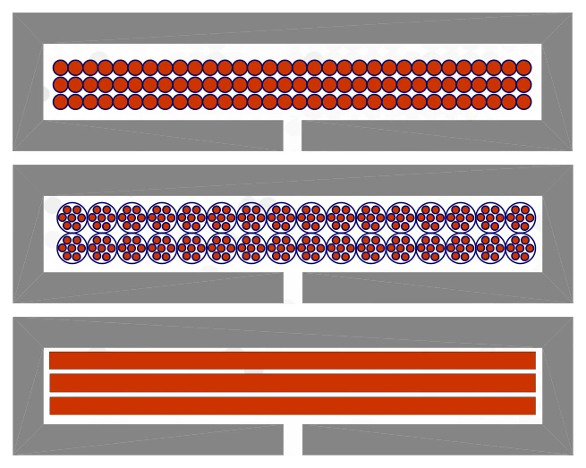
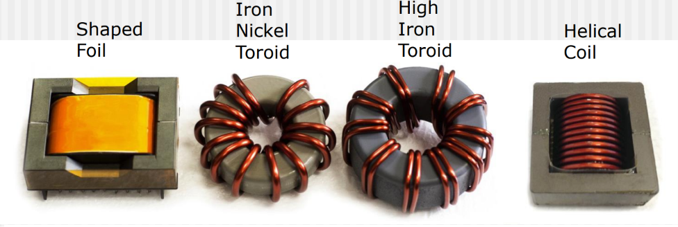
Every SMPS inductor winding is one of three conductors, each with a different cost-and-loss profile:
- Solid wire: lowest cost, low DC resistance, easy to wind, but the highest AC winding loss as frequency rises.
- Litz wire: potential for very low AC loss, but the highest cost and a higher DC resistance, with a practical ceiling around 500 kHz before cost and loss make it impractical.
- Foil: inexpensive, very low DC resistance, and potential for low AC loss. In its shaped (cutout) form, foil extends its low-loss range further, which is what makes it WCM’s default for gapped inductors.
The reason no single winding always wins is the proximity effect: in a gapped inductor, the strong local field near the core gap induces eddy currents in the copper, driving AC resistance up. How badly that hurts depends on how much AC ripple the inductor carries and how fast it switches. The physics behind that is covered in reducing winding losses in high-frequency inductors.
The Deciding Number: Ripple Times Frequency
For a gapped inductor, shaped cutout foil is the lowest-loss winding up to a ripple-frequency product of about 7000 (%ripple × kHz). Below that, the gap-field losses are manageable and foil’s low DC resistance and low cost win. Above it, the AC loss grows enough that litz wire’s finely divided strands pull ahead.
Because the threshold is a product, it moves with frequency. The table below gives the ripple magnitude above which litz has lower loss than copper foil, for a representative 4-turn boost inductor:
| Switching frequency | Ripple where litz beats foil | Ripple-frequency product |
|---|---|---|
| 100 kHz | 63% | 6300 |
| 200 kHz | 37% | 7400 |
| 300 kHz | 26% | 7800 |
| 400 kHz | 23% | 9200 |
| 500 kHz | 20% | 10000 |
| 1 MHz | 18% | 18000 |
| 2 MHz | 15% | 30000 |
The practical reading: at 100 kHz you can run 63% ripple before litz is worth it, but at 500 kHz the crossover is down to 20% ripple. Both foil and litz stay usable up to about 2 MHz as long as ripple is under 20%.
Cost: Why Litz Is the Expensive Answer
Litz wire buys low AC loss at a steep price. In the designs behind this analysis, litz wire was 60 to 70 percent of the total material cost, and that cost rises exponentially with frequency as the strands get finer and more numerous. Foil, by contrast, is inexpensive. That is the real value of shaped cutout foil: below the roughly 7000 ripple-frequency threshold, it delivers litz-like loss at foil cost. For the measured foil-cut loss and cost data against litz, see the low AC resistance foil-cut inductor; for how to specify litz when it is the right call, see litz wire design for high-frequency windings.
Shaped Cutout Foil: The WCM Option
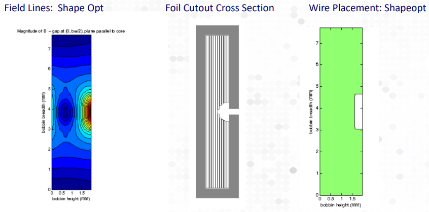
For a gapped inductor, shaped cutout foil has lower loss than full-width foil at the same copper cross-section, because the copper is removed exactly where the gap field would otherwise force the most loss. WCM developed the shaped/cutout foil winding with Dartmouth’s Thayer School of Engineering; the cutout foil patent is issued to Dartmouth and WCM, with a second patent pending. WCM builds its shaped-foil inductors on low-loss gapped ferrite cores, and the family of standard parts is described in boost inductor design.
Inductors and Transformers Are Different Problems
The winding decision is not the same for a transformer. In a transformer, the designer can interleave primary and secondary windings to cut proximity loss, and high-power designs often need many turns, which makes foil-thickness and layer optimization the critical levers. In a gapped inductor, interleaving does not apply and the gap field dominates, so the choice comes down to shaping the foil or moving to litz.
Either way, the design is verified, not guessed: WCM measures DC resistance, tests ESR across frequency to compare windings, and models options with the appropriate tool (Dowell for solid wire and foil, LitzOpt for litz, ShapeOpt for shaped windings, and ANSYS for full 2D/3D field solving). For the full design, build, and test capability set, see the WCM capabilities overview.
When standard components don’t fit your needs, our teams will engineer a solution.
FAQ
For a gapped SMPS inductor, the deciding factor is the ripple-frequency product: percent ripple current times switching frequency in kilohertz. Up to a product of about 7000, shaped cutout foil is the lowest-loss winding; above that, litz wire has lower loss but costs far more. Solid wire is the cheapest option but has the highest AC loss, so it suits low-frequency or low-ripple designs. The winding cannot be chosen from frequency alone, because ripple magnitude changes the answer.
The ripple-frequency product is percent ripple multiplied by switching frequency in kilohertz. For a gapped inductor, shaped cutout foil is the lowest-loss winding up to a product of about 7000. Because it is a product, the ripple crossover falls as frequency rises: about 63% ripple at 100 kHz, 26% at 300 kHz, and 20% at 500 kHz. Both foil and litz remain usable up to about 2 MHz as long as ripple stays under 20%.
Litz wire divides the conductor into many fine, individually insulated strands to reduce AC loss, and that construction is costly. In the designs behind this analysis, litz was 60 to 70 percent of the total material cost, and the cost rises exponentially with frequency as the strands get finer and more numerous. This is why shaped cutout foil is attractive below the roughly 7000 ripple-frequency threshold: it delivers litz-like loss at foil cost.
Shaped cutout foil is a foil winding with copper removed near the core gap, where the gap’s strong local field would otherwise drive high AC loss. At the same copper cross-section, shaped cutout foil has lower loss than full-width foil in a gapped inductor. WCM developed it with Dartmouth’s Thayer School of Engineering; the cutout foil patent is issued to Dartmouth and WCM, with a second patent pending.
Yes. In a transformer, windings can be interleaved to reduce proximity loss, and high-power designs often need many turns, so foil-thickness and layer optimization become the critical levers. In a gapped inductor, interleaving does not apply and the gap field dominates, so the decision is between shaping the foil and moving to litz. WCM verifies either choice by measuring DC resistance and ESR across frequency and modeling with tools such as Dowell, LitzOpt, ShapeOpt, and ANSYS.
 Foil vs Litz vs Wire: Choosing an SMPS Inductor Winding
 Contact Us