How Do You Choose Litz Wire for High-Frequency Windings?
Published by West Coast Magnetics, June 2026, based on our 2009 presentation “Winding Losses in High-Frequency Transformers” (available for download below); content reviewed and confirmed current as of publication.
Litz wire lowers AC winding loss by dividing a conductor into many fine, individually insulated strands, so each strand stays within about one skin depth and the eddy-current losses that drive AC resistance largely cancel. Choosing it well comes down to two decisions: make the strands fine enough for the operating frequency, and use the right number of them. Picking a strand gauge from a frequency table alone is a common trap, because over-stranding raises cost and can actually raise loss. This guide covers how to set both, and where litz stops being the right answer.
Litz wire is a multi-strand conductor (strands typically 24 to 50 AWG) twisted so that each strand carries a nearly equal share of current, reducing the skin-effect and proximity-effect losses that make a solid conductor’s AC resistance climb with frequency. Skin depth is the distance below a conductor’s surface at which the current density falls to about 37% (1/e) of its surface value; it sets how fine each strand must be.
Why Does Litz Wire Reduce AC Winding Loss?
A winding has two loss terms: a DC term (I squared times DC resistance) and an AC term from skin effect and proximity effect that grows with frequency. Skin effect forces current toward a conductor’s surface, so above a certain frequency only the outer shell within one skin depth carries current and the effective cross-section shrinks. Proximity effect adds loss induced by the magnetic field of adjacent turns and windings, and in a multilayer winding it can dominate: at a conductor thickness of twice the skin depth, proximity effect can raise AC resistance to roughly 28 times the DC value, where skin effect alone would add only about 2%.
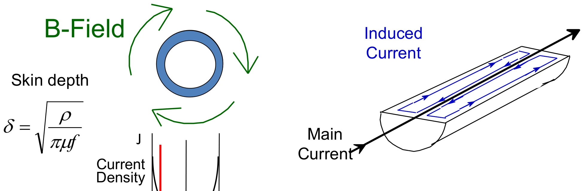
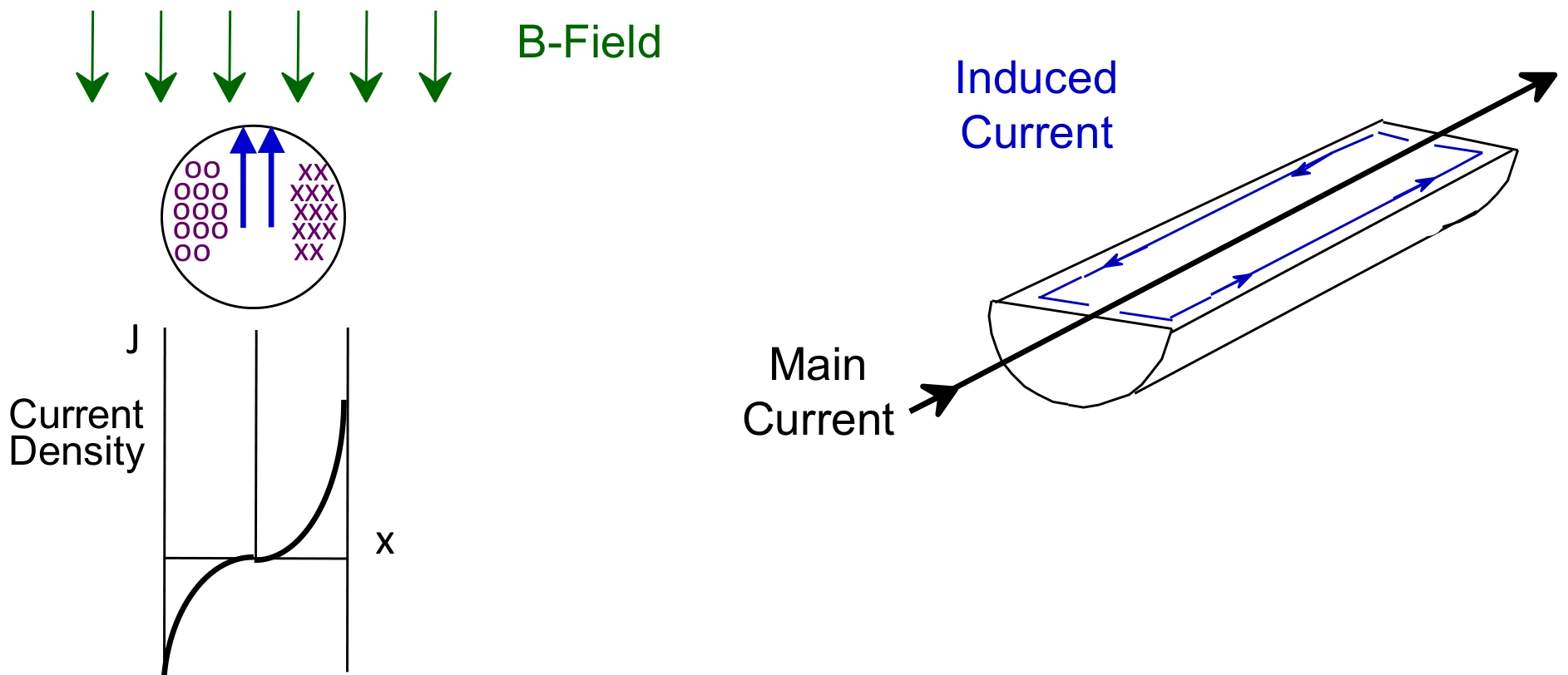
Litz attacks both. If each strand is fine enough relative to skin depth, eddy-current losses are largely eliminated and the winding loss falls back toward the simple I squared times DC resistance. That is why litz manages high-frequency winding losses effectively up to about 1 MHz. The tradeoff is that litz has low AC resistance and low DC resistance but is the highest-cost winding option, and dividing the copper into strands raises DC resistance relative to a solid foil winding.
How Fine Do the Strands Need to Be?
The strand diameter is set by skin depth. For copper, skin depth is approximately:
Δ = 6.62 / √f cm, with frequency f in Hz.
The table below gives the result across the SMPS range. The right column is the wire gauge whose diameter equals one skin depth at that frequency.
| Frequency | Skin depth (cm) | Skin depth (in) | Gauge with diameter = skin depth |
|---|---|---|---|
| 1 kHz | 0.2093 | 0.0824 | 12 AWG |
| 10 kHz | 0.0662 | 0.0261 | 22 AWG |
| 25 kHz | 0.0419 | 0.0165 | 26 AWG |
| 50 kHz | 0.0296 | 0.0117 | 29 AWG |
| 100 kHz | 0.0209 | 0.0082 | 32 AWG |
| 200 kHz | 0.0148 | 0.0058 | 35 AWG |
| 300 kHz | 0.0121 | 0.0048 | 37 AWG |
Copper skin depth versus frequency (West Coast Magnetics).
At 200 kHz the skin depth is 0.0148 cm, which corresponds to 35 AWG. A single 35 AWG strand carries very little current, which is exactly why the conductor is built from many such strands in parallel. As a practical starting point, designers use 24 AWG and finer strands to limit AC losses above 10 kHz, with 36 to 40 AWG common below 100 kHz and 42 to 44 AWG at higher frequencies. Finer strands cut AC loss further, but the price of litz increases significantly as the strand gauge is reduced, so finer is not automatically better.
The benefit of stranding is easiest to see as a crossover frequency, the point where the conductor’s diameter equals one skin depth. A 10 AWG solid wire reaches that point near 0.65 kHz, so above a few kHz most of its copper is unused. Replacing it with 66 strands of 28 AWG litz pushes the crossover to about 42.8 kHz, and 210 strands of 33 AWG moves it past 138 kHz. Each finer, more numerous construction keeps more of the copper usable at higher frequency.
How Many Strands Should You Use?
Strand count is the harder half of the problem, and it is where simple recommendations backfire. Charles Sullivan at Dartmouth’s Thayer School of Engineering published a simplified design method for litz wire that needs only four inputs: the skin depth at the operating frequency, the number of turns in the winding section, the breadth of the core window, and a constant read from a table for the chosen strand diameter. From those it returns a recommended number of strands for each candidate strand diameter, so the designer can compare a few constructions rather than guess.
The reason a strand-diameter-by-frequency table alone is dangerous is that it ignores the number of turns and the window geometry, both of which change how many strands minimize total loss. Too few strands leaves AC loss on the table; too many raises DC resistance and cost without a matching benefit, and can increase total loss.
For a full optimization across multiple windings and arbitrary current waveforms, WCM and Dartmouth use LitzOpt, a free tool developed by Jennifer Pollock and Charles Sullivan. LitzOpt uses the squared-field-derivative (SFD) method, which computes per-strand loss from the rate of change of the local magnetic field rather than from a single resistance factor, so it handles real PWM waveforms and field variation across the window that a hand calculation cannot.
What Does Litz Cost, and When Should You Stop Using It?
Litz is effective but expensive. In WCM’s case studies, litz wire is typically 60 to 70% of the total material cost, and that cost rises exponentially as the operating frequency (and therefore the required number of fine strands) increases. Litz also stops being sufficient above about 1 MHz, where even fine stranding cannot keep losses down and a different winding approach is needed.
Those two limits are why WCM developed shaped foil technology with Dartmouth: it combines the very low DC resistance of a foil winding with AC resistance close to litz, at lower cost. For gapped inductors specifically, the foil-cut winding reaches a similar AC-resistance advantage with copper removed near the gap, at a material cost well below litz. Litz remains the right choice for many transformer windings, where it is one of the four standard conductor options covered in SMPS transformer winding design.
When Should You Have WCM Specify the Litz Construction?
Strand diameter, strand count, the number of turns, and the winding geometry all interact, and the cost penalty for over-specifying grows with frequency. WCM has worked with the Dartmouth team behind the litz design methods for years and builds high-frequency windings to a specification rather than a guess. When the requirement is a specific inductance or turns ratio, current, ripple, and frequency, WCM’s custom magnetics team will choose the construction (litz, foil, or shaped foil) and the core together for the lowest total loss at your operating point.
FAQ
Set two things. First, the strand diameter, which must be fine enough for the operating frequency: copper skin depth in cm is about 6.62 divided by the square root of the frequency in hertz, so at 200 kHz the skin depth is 0.0148 cm and a strand near 35 AWG keeps the conductor within one skin depth. Second, the number of strands, which depends on the turns count and window geometry, not frequency alone. Use a method that accounts for all of these, such as the Sullivan simplified design method or the LitzOpt tool, rather than a strand-diameter-by-frequency table.
As a starting point, 24 AWG and finer limits AC loss above 10 kHz, with 36 to 40 AWG common below 100 kHz and 42 to 44 AWG at higher frequencies. Finer strands reduce AC loss but cost significantly more, so the goal is the coarsest strand that still keeps each strand within about one skin depth at the operating frequency.
Because strand count, not diameter alone, sets the loss, and the right count depends on the number of turns and the core window. A diameter-only table can lead to too many or too few strands, raising cost and in some cases raising total loss. A method that includes turns and window breadth, like the Sullivan simplified method, gives a recommended strand count for each candidate diameter so you can compare real constructions.
Litz manages high-frequency winding losses effectively up to about 1 MHz. Above that, even fine stranding cannot hold losses down and a different winding approach is required. Cost also rises exponentially with frequency because more, finer strands are needed.
Litz gives low AC and DC resistance but is the highest-cost winding option, typically 60 to 70% of material cost in WCM case studies. For gapped inductors, shaped foil and foil-cut windings reach AC resistance close to litz at lower cost, so litz is often best reserved for transformer windings and cases where its specific advantages are needed.
 Contact Us