How Do You Make a Magnetic Component Smaller, Lighter, and More Efficient?
Published by West Coast Magnetics, July 2026, based on a magnetics-design chalk talk by Prof. Charles Sullivan of Dartmouth (available for download below); content reviewed and confirmed current as of publication.
You make a transformer or inductor smaller, lighter, and more efficient by treating the system objectives, efficiency, cost, size, weight, reliability, and time to market, as fungible: any reduction in loss or cost can be spent on whichever objective the application prioritizes. The main lever is high-frequency winding loss. Reduce it, and you can raise the switching frequency to shrink the core, or hold the size and bank the efficiency instead. The design work is choosing where to spend the gain.
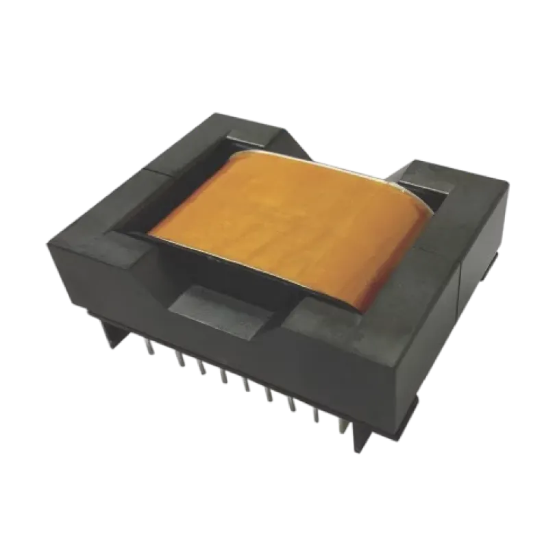
A system objective is a goal defined at the converter or product level, not the component level: efficiency, cost, size, weight, reliability, or time to market. A fungible benefit means an improvement in one place can be traded for another: lower winding loss can be taken as higher efficiency, or converted into smaller size by raising the switching frequency. The point of magnetics optimization is to decide which objective gets the benefit.
Design Around System Objectives, Not Just the Part
A magnetic component is rarely optimized in isolation. It is optimized against the objectives of the system it sits in: efficiency, cost, size, reliability, weight, and time to market. Those objectives compete, so the useful question is not “what is the best inductor?” but “what does this application most need, and what is it willing to trade to get it?”
There are three paths to improving a magnetic component, and they are interchangeable:
- Model the losses accurately, so the design is optimized against reality rather than a worst-case guess.
- Reduce the losses at a similar cost.
- Reduce the cost at a similar efficiency.
The benefits are fungible: either improvement can be spent on either objective. A winding change that cuts loss can be cashed in as efficiency, or the freed-up thermal headroom can be used to shrink the part. This framing comes from Prof. Charles Sullivan’s magnetics design work at Dartmouth’s Thayer School of Engineering; his chalk talk on the subject is available as the download on this page.
The System-Level Levers
The biggest decisions that set a magnetic component’s size, loss, and cost are made above the component, in the converter design:
- Switching frequency: raising it shrinks the magnetics, because less energy needs to be stored per cycle, but it raises the frequency-dependent losses the winding and core must handle.
- Inductance and turns ratio: these trade ripple current and core flux against copper, and set how much winding fits in the window.
Each choice has to be weighed on two sides: its impact on the magnetics (size, loss, cost) and its impact on the rest of the circuit (performance, loss, cost). The right answer depends on which objective the application prioritizes, so the frequency and topology are chosen interactively with the magnetics, not handed to it.
Once the operating point is set, the magnetic component itself is designed on three layers: component design (size, shape, cooling strategy, and the winding-versus-core-loss split), winding design (DC resistance, high-frequency loss, and capacitance), and core selection (core loss and saturation). For the transformer version of this problem, see the SMPS transformer design guide; for boost and buck inductors, see boost inductor design.
Why High-Frequency Winding Loss Is the Binding Constraint
The reason you cannot simply keep raising the frequency to shrink the part is high-frequency winding loss. As frequency rises, skin effect and proximity effect push current into a thin layer of the conductor, so the AC resistance climbs well above the DC value, and in a multi-layer winding the proximity effect can raise AC resistance many times over. That loss becomes heat, and heat sets the size floor.
This is the constraint that magnetics design has to beat, and the mechanisms and the winding solutions are covered in depth in three companion articles: reducing winding losses in high-frequency inductors, the low AC resistance foil-cut inductor, and litz wire design for high-frequency windings. The short version: reduce the number of winding layers, interleave where the topology allows (transformers), and shape the field or the conductor where it does not (inductors).
WCM Shaped Foil: Single-Layer Behavior for Smaller, Cooler Inductors
Inductors are the harder case. Interleaving does not apply, and the core gap concentrates and distorts the field, which drives proximity loss. WCM’s shaped-foil winding addresses this directly: it exhibits single-layer behavior with almost no proximity effect and low DC resistance, and the size of the foil cutout is optimized for the AC-versus-DC resistance tradeoff. A fully shaped foil looks expensive to make, but WCM uses a proprietary alternative shape that is significantly easier to manufacture.
The practical payoff maps straight back to the system objectives: a winding with low AC resistance at high frequency lets the same inductor run at a higher switching frequency, which shrinks the core and the overall part, or run cooler at the same size, which buys efficiency and reliability. That is what “smaller, lighter, more efficient” reduces to in an inductor.
Bringing It Together
Making magnetics smaller and lighter is a sequence of deliberate trades, not a single trick. Decide which system objective the application prioritizes, choose the switching frequency and topology with the magnetics in the loop, then select the winding and core technology that spends the loss budget where it matters. Because WCM designs and builds its own transformers and inductors in-house, the winding technology and the design tradeoffs are chosen together, to the customer’s priority. For the full design, build, and test capability set, see the WCM capabilities overview.
When standard components don’t fit your needs, our teams will engineer a solution.
FAQ
Magnetic components are optimized against system-level objectives: efficiency, cost, size, reliability, weight, and time to market. These objectives compete, so a design is not simply “the best inductor” but the one that meets the application’s priority while trading away what matters least. The benefits are fungible, meaning a reduction in loss or cost can be spent on whichever objective the application values most.
Raising the switching frequency shrinks the magnetics, because less energy has to be stored per cycle, so the core can be smaller. The tradeoff is that higher frequency increases the frequency-dependent losses in the winding and core. How far you can push the frequency to shrink the part is limited by how well the winding controls high-frequency loss, which is why low-AC-resistance windings are what enable smaller, higher-frequency designs.
As frequency rises, skin effect and proximity effect confine current to a thin region of the conductor, raising AC resistance well above the DC value; in a multi-layer winding the proximity effect can multiply AC resistance many times. That extra resistance turns into heat, and the amount of heat a part can dissipate sets its minimum size. Reducing high-frequency winding loss is therefore the key to shrinking the component without overheating it.
A fungible benefit is an improvement that can be applied to more than one objective. If a winding change lowers loss, that gain can be taken as higher efficiency, or it can be converted into a smaller part by raising the switching frequency and using the freed thermal headroom. Recognizing that loss and cost improvements are interchangeable is what lets a designer aim the optimization at the objective the application actually needs.
WCM’s shaped-foil winding gives single-layer behavior with almost no proximity effect and low DC resistance, with the foil cutout sized to optimize the AC-versus-DC resistance tradeoff. Low AC resistance at high frequency lets an inductor run at a higher switching frequency (shrinking the core) or run cooler at the same size (gaining efficiency and reliability). WCM uses a proprietary shaped-foil form that is significantly easier to manufacture than the standard approach.
 Magnetics Design for System Objectives: Smaller, Lighter, More Efficient
 Contact Us