Boost Inductor Design: Choosing the Core and Winding for Lowest Cost and Loss
Published by West Coast Magnetics, June 2026, based on our boost inductor design paper (available for download below); content reviewed and confirmed current as of publication.
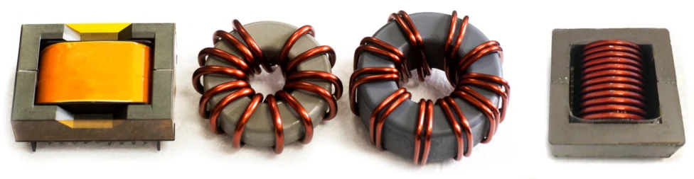
The lowest-cost, lowest-loss boost inductor for medium-to-high-power SMPS converters is usually a gapped manganese-zinc ferrite E-core wound with West Coast Magnetics’ Shaped Foil Technology. In a controlled WCM benchmark (10 µH, 55 A rms, 65 A peak), that combination ran less than half the loss of two conventional powdered-core toroids built to the same requirement, at a fraction of the cost and in a smaller volume. Boost inductor design comes down to two coupled choices: the core material, which sets loss density, saturation flux density, and cost per unit volume, and the winding, which sets the split between DC and AC copper loss. Get both right together and you can run higher ripple and higher frequency without the loss penalty, which is what lets you shrink the part.
Boost inductor design is the selection of a core material and a winding construction for the energy-storage inductor in a boost (or buck) SMPS converter, optimized so the inductor carries its DC current and AC ripple at the target frequency with the lowest total of core loss plus winding loss, at the lowest cost and volume. The two loss components pull in different directions, so the core and the winding have to be chosen together.
What Drives Cost and Loss in a Boost Inductor
Total inductor loss is the sum of core loss and winding loss. Core loss is set by the core material’s loss density (in mW/cm³) at the operating flux swing and frequency. Winding loss is the copper, and it has a DC resistance term and an AC resistance term from skin and proximity effects that climbs with frequency and ripple current. For the underlying physics of why that AC term dominates at switch-mode frequencies, and how each conductor type behaves, see our companion article on how to reduce winding losses in high-frequency inductors. This article stays on the design-level question: which core and which winding to pick for a boost inductor across the medium-to-high power range (roughly 1 kW to 100 kW) at switch-mode frequencies above 10 kHz.
Three core variables govern the choice: loss density, saturation flux density, and cost per cm³ of material. A core with low loss density keeps core loss down. A core with high saturation flux density stores more energy in less volume, so a lower-Bsat material needs a longer magnetic path length to handle the same peak current without saturating. Cost per cm³ then decides whether the volume penalty is worth it.
How Do Boost Inductor Core Materials Compare?
Among the common core materials, manganese-zinc ferrite has the lowest loss density, followed by nickel-iron, then the Fe-Al-Si (iron-aluminum-silicon) powdered core, with pure iron powder having the greatest losses. On cost, a ferrite core sits slightly above high-iron-content powdered cores and below powdered cores that add nickel or silicon and aluminum for higher performance. The main disadvantage of ferrite is its much lower saturation flux density, which requires a longer magnetic path length to avoid saturating at peak current.
Amorphous, nanocrystalline, and MPP cores are notably more expensive than ferrite and powdered cores, so when cost is a primary objective they are usually excluded from the comparison. Likewise, litz wire is significantly more expensive than solid wire and copper foil. The practical trade space for a cost-and-loss-driven boost inductor is therefore gapped ferrite versus powdered cores, paired with solid wire, foil, or shaped foil.
| Core material | Loss density | Cost per cm³ | Saturation flux density |
|---|---|---|---|
| Manganese-zinc ferrite (gapped) | Lowest | Slightly above high-iron powder | Low (needs longer magnetic path) |
| Nickel-iron powder | Higher than ferrite | Higher (nickel added) | Higher than ferrite |
| Fe-Al-Si powder | Higher than nickel-iron | Higher (Si/Al added) | Higher than ferrite |
| High-iron-content powder | High | Lowest of the group | Higher than ferrite |
| Pure iron powder | Greatest | Low | Higher than ferrite |
Relative comparison of common boost-inductor core materials. Amorphous, nanocrystalline, and MPP cores are excluded as notably more expensive. Source: WCM boost-inductor design study.
One design caution: a gapped ferrite core’s inductance rolls off more quickly above its rated peak current than a powdered core’s does. The powdered core’s distributed gap gives it a softer saturation knee. When you design a ferrite boost inductor, size it to your limiting operating point and anticipate that faster roll-off above the peak.
Winding Options for a Boost Inductor
The winding choice sets how the copper loss splits between DC and AC. The realistic options for a cost-driven boost inductor are solid wire, copper foil, and shaped foil, with litz available but expensive.
- Solid wire is low cost with low DC resistance, but at high frequency only the outer skin-depth shell carries current, so AC resistance and loss climb with ripple and frequency.
- Copper foil uses the winding window efficiently and gives very low DC resistance, but in a multi-turn winding each turn is a layer, so AC resistance rises and even modest ripple produces significant loss.
- Helical windings can carry high current but, as the benchmark below shows, develop high losses at high ripple. WCM does not wind helical coils; the helical case in the study used standard available products and is included only for comparison.
- Litz wire divides the conductor into many fine strands to cut AC resistance, but it raises DC resistance versus foil and is the highest-cost option.
WCM’s Shaped Foil Technology resolves the foil trade-off. Developed in collaboration with the Thayer School of Engineering at Dartmouth College, it removes copper near the air gap of a foil winding and uses the strong gap fringing field to equalize the AC current distribution across the foil cross-section. The result is a single winding with lower DC resistance than solid wire and AC resistance similar to litz, at very low cost. A related approach, the low-AC-resistance foil-cut inductor, removes copper near the gap to the same end. Both pair the low DC resistance of foil with litz-like AC resistance, which is exactly what a high-ripple boost inductor needs.
The Boost-Inductor Benchmark: Shaped Foil vs. Powdered-Core Toroids
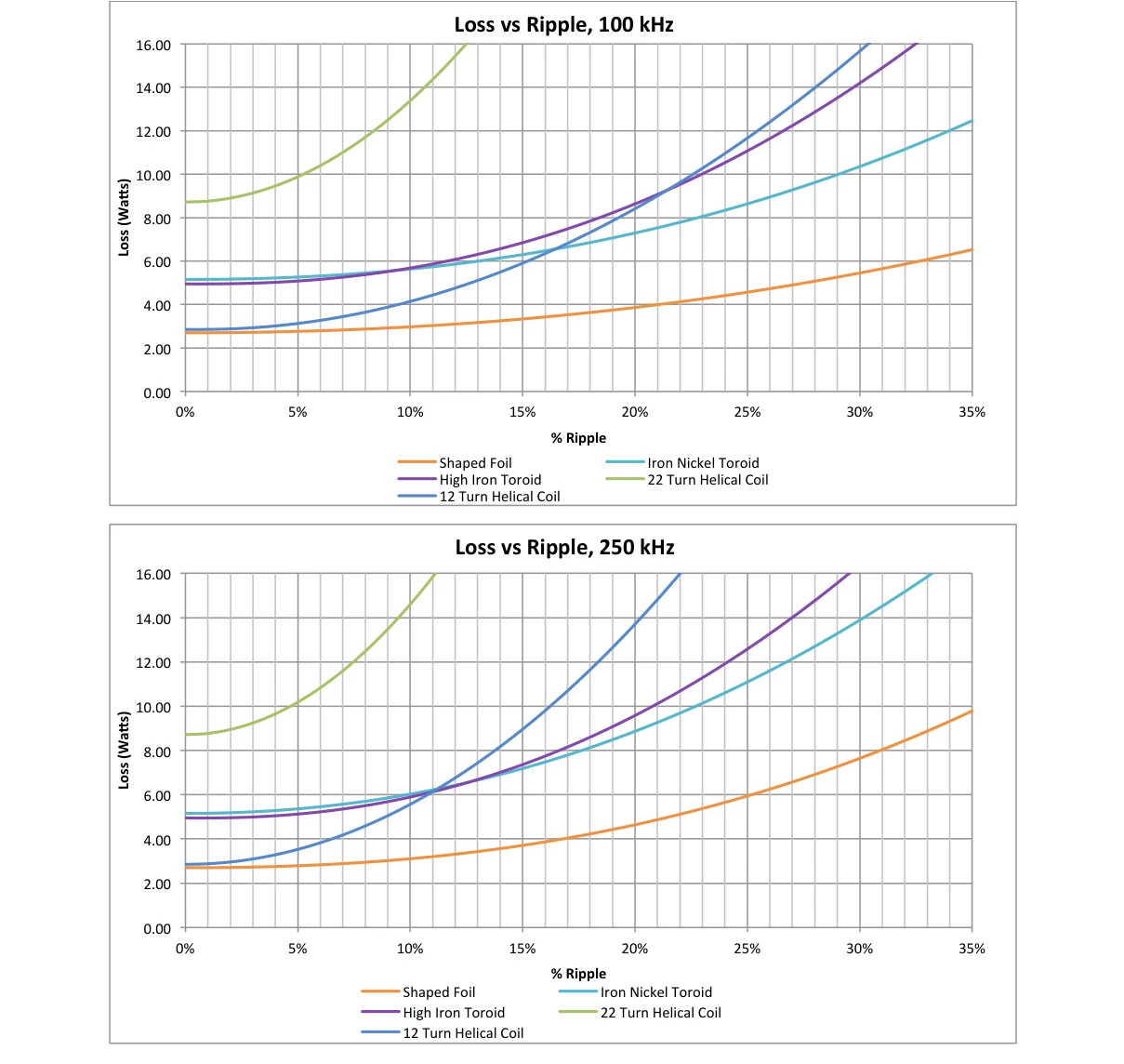
To compare the approaches on equal footing, WCM fixed the design at 10 µH, 55 A rms, and a 65 A peak-current requirement without saturating, a reasonable proxy for a medium-power boost inductor. WCM then built and load-tested four constructions on a Magna-Power SL10 supply with an Agilent 4285 LCR meter, confirming each held 10 µH minimum at 65 A, and summed core loss, DC winding loss, and AC winding loss for each.
The shaped-foil design used a gapped manganese-zinc ferrite E-core (initial permeability 2000) with 6 turns of copper foil at 31,600 circular mils. The two powdered-core toroids were wound with solid wire and sized to hold 10 µH at the 65 A peak.
| Design (10 µH, 55 A rms, 65 A peak) | Loss at 100 kHz | Loss at 250 kHz | Volume | Weight | Cost per part (2022, 1,000-pc quote) |
|---|---|---|---|---|---|
| Shaped foil on gapped ferrite E-core (6 turns foil) | 5.45 W | 7.65 W | 93.72 cm³ | 303.45 g | $4.69 |
| Iron-nickel toroid (13 turns, 7 AWG solid wire) | 10.35 W | 13.89 W | 99.87 cm³ | 295.29 g | $16.18 |
| High-iron toroid (bifilar, 10 turns, 10 AWG) | 14.19 W | 16.40 W | 130.65 cm³ | 475.59 g | $9.48 |
Losses shown at 30% peak-to-peak ripple current. Dollar figures are 2022 1,000-piece quotes, direct from the core manufacturer, and are not current pricing. Request a quote for your build.
The shaped-foil ferrite design was the clear winner: lower loss, lower cost, and smaller volume than either powdered-core alternative. It carried roughly half the loss of the iron-nickel toroid at 100 kHz while costing about a quarter as much. The two helical windings tested on the Fe-Al-Si core (not shown above) ran dramatically higher loss still, up to 50.74 W at 100 kHz for the 22-turn coil, which is why high-ripple helical designs are usually a poor fit.
This is the cost mechanism behind boost inductor design: because the gapped-ferrite-plus-shaped-foil inductor tolerates higher ripple and higher frequency without excessive loss, the converter can run at a higher ripple operating point, which permits a physically smaller inductor. Independent of ripple, the construction also enables high-current designs at 100 kHz and up.
Where Shaped Foil Pays Off Across the Design Space
Beyond the single benchmark, WCM made a controlled, same-core comparison of shaped foil against conventional windings across the design space. The price/performance of shaped foil is a significant improvement over conventional windings for medium-to-high-power buck and boost inductors, across an application power range of roughly 1 kW to 100 kW, operating at peak-to-peak ripple of 10% or more of the DC current value. That 1 kW to 100 kW figure describes the system and application power range these inductors serve, not a rating of any single WCM part. The comparison was run on a 100 µH, 30 A inductor wound on the same gapped ferrite core, sweeping cost against loss for solid wire, litz, thick and thin copper foil, foil-plus-litz, and first- and second-generation shaped foil. Second-generation shaped foil delivered the best cost-versus-loss position of the set.
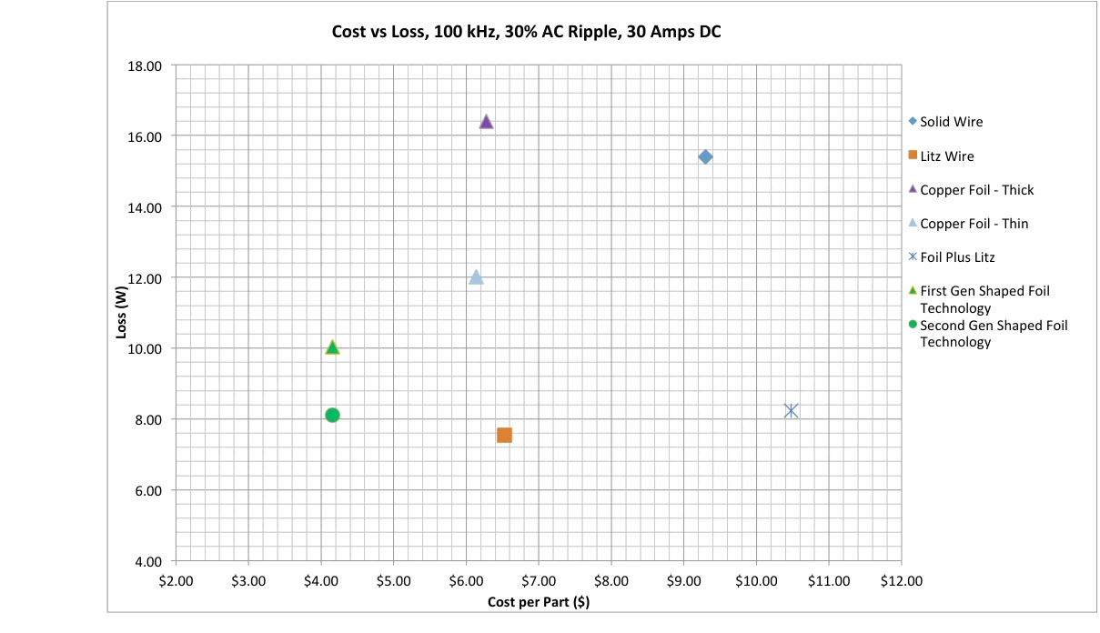
The takeaway for a designer: above about 10% ripple, and at frequencies from roughly 100 kHz upward where AC copper loss would otherwise dominate, a gapped ferrite core with a shaped-foil winding is the construction to specify. Below 10% ripple or at low frequency, the AC-resistance advantage shrinks and a simpler winding may suffice.
From the Study to an Orderable Part
The benchmark constructions map onto WCM’s shaped-foil product families. For chassis-mount and surface-mount high-current designs, the WCM307 shaped-foil chassis power inductor and WCM308 shaped-foil SMD power inductor carry the technology in standard packages. For gapped buck/boost work in tighter envelopes, the compact WCM317 and WCM318 series, the WCM319 series, and the WCM320 power inductors cover a range of current and inductance points. When the constraint is a specific inductance, current, ripple, and footprint, WCM’s custom power inductor team will engineer the core and winding to your spec, drawing on the full inductor design capability and WCM’s design and test capabilities from prototype through production. The Shaped Foil method is patented by Dartmouth College, and WCM is a licensee.
FAQ
For cost-and-loss-driven boost inductor design, a gapped manganese-zinc ferrite core is usually best because it has the lowest loss density of the common core materials and a cost per cm³ only slightly above high-iron powdered cores. Its drawback is a lower saturation flux density, so it needs a longer magnetic path length, and its inductance rolls off faster above the rated peak current than a powdered core. Size to your limiting operating point.
In a WCM benchmark at 10 µH, 55 A rms, and 65 A peak, a gapped ferrite E-core with shaped foil ran lower loss (5.45 W at 100 kHz), lower cost ($4.69 at a 2022 1,000-piece quote), and smaller volume (93.72 cm³) than iron-nickel and high-iron powdered-core toroids built to the same requirement. The ferrite’s low loss density plus a low-AC-resistance winding is what wins.
A winding that controls AC resistance at the gap. Solid wire and plain foil develop high AC loss at high ripple, and litz is the most expensive option. WCM’s Shaped Foil Technology pairs foil’s low DC resistance with litz-like AC resistance at low cost by reshaping the foil near the air gap, which makes it well suited to high-ripple buck and boost inductors.
It is the application and system power range these buck and boost inductors serve across the design space, not the rating of a single WCM part. Individual WCM products are rated up to about 10 kW. The shaped-foil price/performance advantage applies across that application range at peak-to-peak ripple of 10% or more of the DC current.
Shaped foil pays off above about 10% peak-to-peak ripple of the DC current and at frequencies from roughly 100 kHz upward, where AC copper loss would otherwise dominate. Below 10% ripple or at low frequency, the AC-resistance advantage shrinks and a simpler, lower-cost winding may be sufficient.
Because a gapped ferrite core with a shaped-foil winding tolerates higher ripple and higher frequency without excessive loss, the converter can run at a higher ripple operating point. A higher ripple operating point permits a physically smaller inductor for the same energy-storage and current-handling requirement.
 Contact Us