WCM700 RF Filter: A Patented Single-Component, Multi-Channel RF Filter Series
Published by West Coast Magnetics, June 2026, based on our 2025 WCM700-series RF filters whitepaper (available for download below); content reviewed and confirmed current as of publication.
The WCM700 RF filter is West Coast Magnetics’ patented narrow-band, high-impedance RF filter built on a single foil-wound coil instead of discrete inductors and capacitors. It uses the parasitic capacitance of the copper turns as the resonating capacitance, places multiple independent channels on a common core, and is continuously tunable across 2 to 50 MHz (with a 1 to 100 MHz range in development). This page is the WCM700-series technology and specification reference. For the dry-etch application case study, see our RF filter design for semiconductor etch article.
A WCM700 RF filter is a single-component, multi-channel narrow-band RF filter in which the parasitic capacitance of the copper-foil turns is the resonating capacitance, eliminating the need to source and tune a separate inductor and capacitor for a high-impedance parallel-LC response. That single design choice is what makes the series compact, multi-channel, and thermally stable.
How Does the WCM700 RF Filter Work?
Conventional narrow-band RF filtering builds a parallel-LC circuit from a discrete inductor and a discrete capacitor, and the designer fights the parasitic capacitance of the winding to keep the frequency response clean. WCM’s patented technology reverses that. Rather than combating parasitic effects, the design uses them: the parasitic capacitance of the copper turns becomes the resonating capacitance of the inductor.
The result is a single-component design. The engineer no longer sources and tunes a separate inductor and capacitor to build a high-impedance parallel-LC circuit. You specify a target frequency, and WCM builds a unit whose impedance maximum sits at or very near that frequency. (The WCM700 series RF Filters, and portions or components thereof, are covered by, or for use under, U.S. Patents 11,183,985 and 11,831,290, and/or one or more pending U.S. patent applications; see patents.)
Why Put Multiple Channels on a Common Core?
The WCM700 technology places multiple independent filter channels on a common core in nearly identical physical locations. That has two practical payoffs:
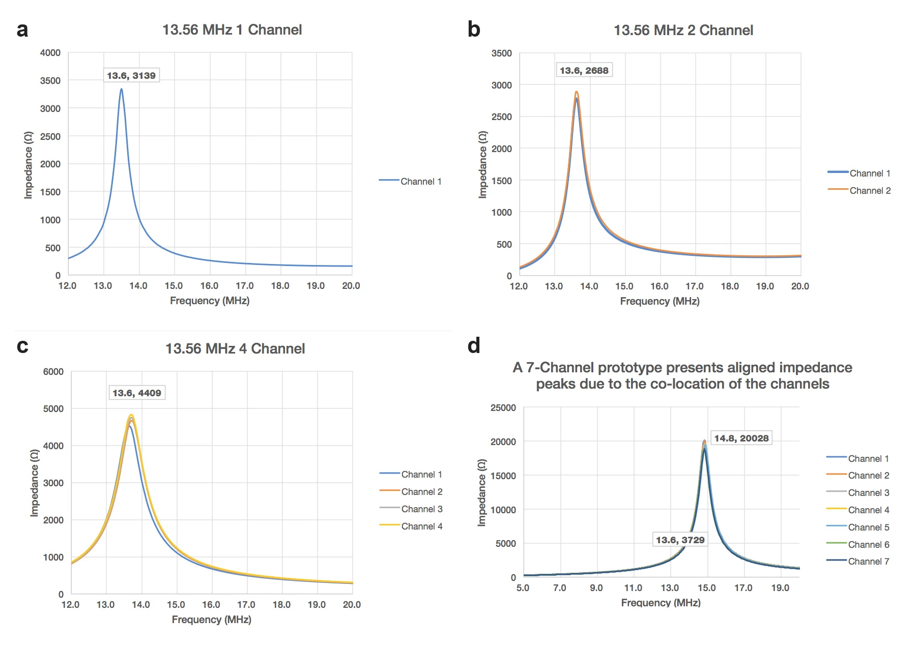
- Channel alignment. In a discrete parallel-LC filter, each channel’s separately located inductor and capacitor do not necessarily line up, so their impedance peaks drift relative to one another. Channels built on a common core align much more closely, and WCM has demonstrated prototypes with up to seven channels showing aligned, high-impedance peaks in a single device.
- Space efficiency. Independent channels are separated by thin, resilient insulation and operate simultaneously, putting several filtered paths into one small package. Channels can also be placed in series to filter independently at multiple frequencies.
This is what lets a multi-heater semiconductor chamber filter each heater circuit independently without spending the board space a bank of discrete filters would demand.
Why a Copper-Foil Winding With No Ferrite Core?
WCM calls the basis of the WCM700 series its advanced compact copper foil technology: the filter uses copper-foil windings and no ferrite core, and both choices are deliberate.
Copper foil uses space more efficiently than round magnet wire. Round wire is subject to the skin effect at radio frequencies, which pushes current to the conductor’s surface and wastes a large proportion of its cross-section. Foil uses more of the available copper cross-section, so the part carries more current with less resistive heating.
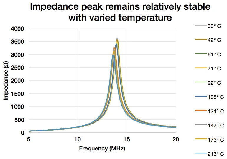
Removing the ferrite core removes the component most sensitive to temperature. Ferrite-cored inductors can see dramatic shifts in magnetic properties and loss as they heat. With no ferrite core, a WCM700 filter stays relatively stable with temperature: only the copper resistance varies, which produces a slight change in impedance rather than the large swing a ferrite-cored parallel-LC filter can exhibit.
What Frequencies Can the WCM700 RF Filter Be Tuned To?
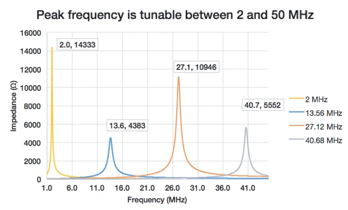
The technology is continuously tunable and is set in the range of 2 to 50 MHz, with expansion into the 1 to 100 MHz range in development. Because the designer specifies the target frequency and WCM places the impedance maximum at or near it, the series lands cleanly on the process frequencies common in semiconductor equipment, such as 13.56 MHz and its related harmonics. The featured WCM700-13-4-20A, for example, is tuned to a self-resonant frequency of 13.56 MHz ±0.5 MHz.
WCM700-Series Specification Ranges (Design-Space Guidance)
The table below is WCM700-series prototype guidance for design engineers. These are series-level ranges and ceilings across builds WCM has prototyped, not the rating of any single part. Use them as a starting point and contact us to scope a unit to your specification.
| Parameter | WCM700-series range / prototype guidance |
|---|---|
| Channels | 1 to 7 |
| RF frequency | 2 to 50 MHz tunable (1 to 100 MHz in development) |
| Impedance | >10 kΩ at resonant frequency |
| DCR | <100 mΩ at 2 MHz; <15 mΩ at >13 MHz (25°C, per channel) |
| Inductance (L) | 5 to 300 µH nominal (25°C, per channel) |
| Capacitance (C) | 10 to 25 pF nominal per channel |
| Channel-to-channel isolation | Up to 3 kV AC |
| Materials | All Class H 155°C unless otherwise requested; filter material supports up to a 200°C rating |
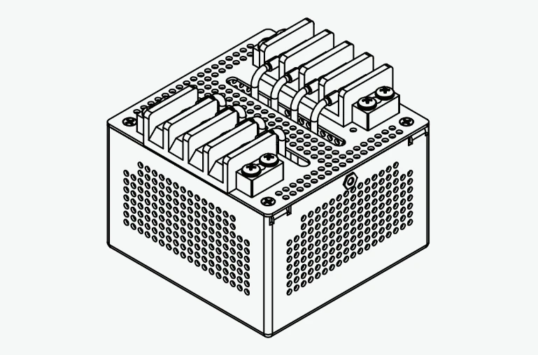
| Prototype dimensions | 4-channel ~3″ x 1.5″ x 1.5″; 7-channel ~4″ x 3.25″ x 1.5″ |
Note: the impedance ceiling (>10 kΩ), the 200°C material rating, and the 1 to 100 MHz range are series and design-space figures. A specific shipping part is rated to its own datasheet values, which may be lower. See the shipping-part lineup below.
The Shipping WCM700 Lineup
WCM publishes several standard 13.56 MHz parts in the family. These are specific part numbers with their own datasheet ratings, distinct from the series ranges above.
| Part number | Channels | Current per channel | Tuned frequency |
|---|---|---|---|
| WCM700-13-2-20A | 2 | 20 A | 13.56 MHz |
| WCM700-13-2-50A | 2 | 50 A | 13.56 MHz |
| WCM700-13-4-20A | 4 | 20 A | 13.56 MHz |
The four-channel WCM700-13-4-20A is the family’s featured part. It puts four independently filtered 20 A channels in one compact package, each with very high narrow-band impedance at 13.56 MHz. Its datasheet (rev. 001) specifies the following.
| Parameter | WCM700-13-4-20A |
|---|---|
| Channels | 4 independent |
| Tuned frequency (SRF) | 13.56 MHz ±0.5 MHz |
| Current rating per channel | 20 A |
| Impedance | >4.5 kΩ at 13.56 MHz |
| Inductance per channel | 6.12 µH nominal at 100 kHz |
| DCR per channel | 15.6 mΩ nominal |
| Channel-to-channel isolation | 2.5 kV AC / 3.5 kV DC |
| Channel-to-chassis isolation | 6 kV DC |
| Materials temperature rating | 130°C |
| Enclosure | Aluminum 5052, alodine finish |
Specifications per the WCM700-13-4-20A datasheet (rev. 001). Note the contrast with the series ranges above: the shipping part is rated >4.5 kΩ at 13.56 MHz and uses materials rated to 130°C, while >10 kΩ and 200°C are series and high-temperature-build ceilings, not this part’s rating.
For how the WCM700-13-4-20A is deployed in a real multi-heater dry-etch tool, see our companion article, RF filter design for semiconductor etch. For the full filter offering, see RF filters.
FAQ
It is a patented, single-component, multi-channel narrow-band RF filter from West Coast Magnetics. Instead of a discrete inductor and capacitor, it uses the parasitic capacitance of its copper-foil turns as the resonating capacitance, giving a high-impedance parallel-LC response in one foil-wound part. The series is continuously tunable across 2 to 50 MHz, with a 1 to 100 MHz range in development.
A discrete filter combines a separate inductor and capacitor, and the designer must source, match, and tune both while fighting winding parasitics. The WCM700 turns the parasitic capacitance into the resonating element, so it is a single part with no subcomponent tuning. Multiple channels share a common core, which aligns their impedance peaks far better than separately located discrete parts, and there is no ferrite core to shift with temperature.
WCM has prototyped 1 to 7 channels on a common core, with each channel separated by thin, resilient insulation so they operate simultaneously. The series supports channel-to-channel isolation up to 3 kV AC. Specific shipping parts carry their own ratings; the WCM700-13-4-20A, for example, provides 2.5 kV AC / 3.5 kV DC channel-to-channel and 6 kV DC channel-to-chassis isolation.
The WCM700-13-4-20A is a four-channel 13.56 MHz filter. Per its datasheet (rev. 001): 4 independent channels, 20 A per channel, SRF 13.56 MHz ±0.5 MHz, impedance >4.5 kΩ at 13.56 MHz, 6.12 µH nominal per channel at 100 kHz, DCR 15.6 mΩ, 2.5 kV AC / 3.5 kV DC channel-to-channel isolation, 6 kV DC channel-to-chassis, materials rated to 130°C, and an aluminum 5052 alodine enclosure.
The whitepaper figures are series-level and design-space ceilings across builds WCM has prototyped: impedance >10 kΩ at resonance, materials supporting a 200°C rating, and a 1 to 100 MHz frequency range in development. A specific shipping part is rated to its own datasheet. The WCM700-13-4-20A is rated >4.5 kΩ at 13.56 MHz with materials rated to 130°C. Always use the part datasheet for a specific part number.
Yes. The technology is continuously tunable, set in the 2 to 50 MHz range today with a 1 to 100 MHz range in development. You specify the target frequency, and WCM builds a unit with its impedance maximum at or very near it, including the 13.56 MHz process frequency and its related harmonics used in semiconductor equipment.
Yes. The WCM700 series RF Filters, and portions or components thereof, are covered by, or for use under, U.S. Patents 11,183,985 and 11,831,290, and/or one or more pending U.S. patent applications. See our patents page.
 Contact Us