RF Filter Design for Semiconductor Etch: WCM’s 13.56 MHz Multi-Channel Filters
Published by West Coast Magnetics, June 2026, based on our 2025 company newsletter; content reviewed and confirmed current as of publication.
West Coast Magnetics designs high-power, narrow-band RF filters for semiconductor dry-etch tools. These components keep clean power flowing to in-chamber heaters while containing the high-frequency RF energy used to drive the plasma. We design and manufacture our own inductive components in-house, which lets us tune a filter to a system’s exact electrical, thermal, and physical constraints rather than forcing an off-the-shelf part to fit. The WCM700-13-4-20A, a four-channel filter built for multi-heater etch setups, is one example.
What Is an RF Filter?
An RF filter is an assembly of inductors and capacitors packaged in an enclosure to control radio-frequency signals. It is not a single magnetic component, it is an assembly. In semiconductor etch and deposition tools, an RF filter passes the power a load needs while blocking the high-frequency energy that drives the plasma, so that energy stays in the chamber and out of the supporting circuitry. WCM’s RF filters are tuned to a specific frequency (commonly 13.56 MHz, with related process frequencies such as 27.12 MHz and 40.68 MHz) to deliver high impedance at that frequency and reject it from the power path.
The RF Filter Challenge in Semiconductor Process Equipment
Dry etching is a core step in semiconductor manufacturing. Instead of liquid chemicals, it uses plasma to etch nanometer-scale patterns onto silicon wafers. The plasma is formed by applying high-power radio-frequency energy to a carefully controlled gas mixture inside a vacuum chamber, and as the ions strike the wafer surface they carve features at extremely fine scale.
That creates a hard filtering problem. Critical components inside the chamber (heaters, for example) need clean power, but the RF energy sustaining the plasma must stay contained and out of the supporting circuitry. The filter has to pass what should pass and block what should be blocked, all in a tight, electrically noisy, thermally demanding envelope. In multi-heater designs the filter also has to keep each heater circuit filtered independently, with clean separation between channels, inside the limited physical and electrical space a dry-etch system allows.
Why We Design RF Filters In-House
We design and manufacture our own inductive components in-house, which lets us tune a filter to a system’s exact electrical, thermal, and physical constraints. Combined with a team that has a semiconductor background (particularly in dry-etch tools), that gives us a clear read on what these systems actually demand. When standard parts can’t meet an application-specific requirement, we engineer the part to the requirement instead of the other way around. You can see the broader scope of our in-house design, manufacturing, and test work on our capabilities page, and the markets we serve for application context.
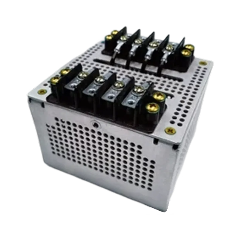
The Featured Design: WCM700-13-4-20A
The WCM700-13-4-20A is purpose-built for multi-heater etch setups. It puts four independently filtered 20-amp channels in one compact part, each with very high narrow-band impedance at 13.56 MHz.
| Parameter | WCM700-13-4-20A |
|---|---|
| Channels | 4 independent |
| Tuned frequency (SRF) | 13.56 MHz ±0.5 MHz |
| Current rating per channel | 20 A |
| Impedance | >4.5 kΩ at 13.56 MHz |
| Inductance per channel | 6.12 µH nominal at 100 kHz |
| DCR per channel | 15.6 mΩ nominal |
| Channel-to-channel isolation | 2.5 kV AC / 3.5 kV DC |
| Channel-to-chassis isolation | 6 kV DC |
| Materials temperature rating | 130°C |
| Enclosure | Aluminum 5052, alodine finish |
Specifications per the WCM700-13-4-20A datasheet (rev. 001).
Four independent, well-isolated, high-impedance channels live in a single small package: exactly what a multi-heater chamber needs when board space and clearance are scarce.
The Technology: Parasitic Capacitance, Made Useful
The WCM700 series is built on WCM’s RF filter coil technology, and the core idea reverses conventional practice. Rather than fighting parasitic capacitance, the design uses it: the parasitic capacitance of the copper turns becomes the resonating capacitance of the filter. That makes it a single-component design. The engineer no longer has to source and tune a separate inductor and capacitor to build a high-impedance parallel LC circuit. (The WCM700 series RF Filters are covered by U.S. Patents 11,183,985 and 11,831,290 and/or pending patent applications; see patents.)
This single-component design has four practical consequences:
- Multichannel on a common core. Multiple independent channels sit on a common core, which improves channel-to-channel alignment compared with discrete parallel-LC filters whose separately located parts do not necessarily line up. Channels can also be placed in series to filter independently at multiple frequencies. WCM has demonstrated prototypes with up to seven channels showing aligned, high-impedance peaks in a single device.
- Continuously tunable. The technology is continuously tunable across 2–50 MHz (with a 1–100 MHz range in development). You specify the target frequency, and WCM builds a unit with its impedance maximum at or very near it. That is how a part lands precisely on 13.56 MHz.
- Low loss and space-efficient. The filters use copper foil windings, which use space more efficiently than round magnet wire and are not subject to the skin-effect losses round wire suffers at RF. Using the full copper cross-section means more current with less resistive heating.
- Thermally stable. The technology uses no ferrite core, so it avoids the dramatic shifts in magnetic properties and loss that ferrite-cored LC filters can see with temperature, and impedance stays relatively stable because copper resistance changes only slightly with temperature. Temperature rating depends on the build: the featured WCM700-13-4-20A uses materials rated to 130°C, while high-temperature constructions extend to 200°C.
WCM700-Series Specification Ranges
The values below are WCM700-series prototype guidance for design engineers, not a single part number. We have built prototypes across several frequency ranges; use these as a starting point and contact us to scope a unit to your specification.
| Parameter | WCM700-series / prototype range |
|---|---|
| Channels | 1–7 |
| RF frequency | 2–50 MHz tunable (1–100 MHz in development) |
| Impedance | >10 kΩ at resonant frequency |
| DCR | <100 mΩ at 2 MHz; <15 mΩ at >13 MHz (25°C, per channel) |
| Inductance (L) | 5–300 µH nominal (25°C, per channel) |
| Capacitance (C) | 10–25 pF nominal per channel |
| Channel-to-channel isolation | Up to 3 kV AC |
| Temperature | Build-dependent (featured WCM700-13-4-20A: 130°C; high-temperature builds to 200°C) |
FAQ
An RF filter is an assembly of inductors and capacitors packaged in an enclosure to control radio-frequency signals. It is not a single magnetic component, it is an assembly. In etch and deposition tools, it passes the power a load needs while blocking the high-frequency energy that drives the plasma.
The WCM700-series technology is continuously tunable across 2–50 MHz, with a 1–100 MHz range in development. Filters are commonly tuned to 13.56 MHz for semiconductor etch, with related process frequencies including 27.12 MHz and 40.68 MHz. You specify the target frequency and WCM sets the impedance maximum at or near it.
WCM’s design uses the parasitic capacitance of the copper turns as the resonating capacitance, so a high-impedance parallel LC response is built into one part. You no longer source and tune a separate inductor and capacitor, channel-to-channel alignment improves because the channels share a common core, and the assembly is more compact for space-constrained chambers.
WCM has built prototypes from 1 to 7 channels. Channels sit on a common core for aligned, high-impedance peaks, and the WCM700-series supports channel-to-channel isolation up to 3 kV AC. The featured WCM700-13-4-20A provides four independently filtered 20-amp channels in one compact part.
Copper foil uses the full conductor cross-section, so it carries more current with less resistive heating and avoids the skin-effect losses round magnet wire suffers at RF. With no ferrite core, the filter avoids the sharp shifts in magnetic properties and loss that ferrite-cored LC filters see with temperature; temperature rating then depends on the build (the featured WCM700-13-4-20A is rated to 130°C).
They are used in etch and deposition equipment in the semiconductor industry, where they remove unwanted high-frequency energy from one-, two-, and four-channel power connections while keeping clean power flowing to in-chamber components such as heaters.
 Contact Us