How Do You Measure and Separate Core Loss and Copper Loss in an Inductor?
Published by West Coast Magnetics, July 2026, based on our APEC 2019 presentation on magnetic-component core and copper loss measurement (available for download below); content reviewed and confirmed current as of publication.
You separate an inductor’s total loss into core loss and copper (winding) loss by measuring its complex impedance on an impedance analyzer, then removing the winding-capacitance and core-loss contributions to leave the winding resistance. The impedance analyzer gives you the real and imaginary impedance (Rm and Xm); you then need two more quantities (the winding capacitance Cw and the core’s parallel loss resistance Rp) before you can solve for the winding resistance (Rw). Done carefully it works; done carelessly it produces non-physical numbers that are easy to miss.
Before you start, decide whether the extraction is even worth it. For some devices a simulation is both faster and more accurate than a bench extraction, and every result has to be interpreted carefully because measurement error can produce plausible-looking but wrong numbers. This method builds on the approach in Foo, Stein, and Sullivan’s “A Step-by-Step Guide to Extracting Winding Resistance from an Impedance Measurement” (APEC 2016), and reflects how WCM does the measurement in practice.
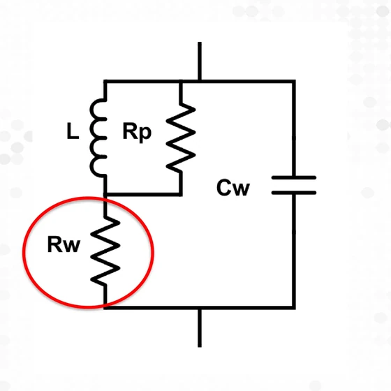
The model. Treat the inductor as a winding resistance Rw in series with the inductance L, a core-loss resistance Rp in parallel with L, and a winding capacitance Cw across the whole network. The impedance analyzer sees all four at once; the job is to strip Cw and Rp away to isolate Rw.
Step 1: Measure the Complex Impedance
Using an impedance analyzer (the source example used an HP4285A), measure the device at the frequency of interest and read off the real and imaginary parts of the impedance, Rm and Xm (both extractable from the measured impedance magnitude and phase angle). Use a short fixture with the current-injection and voltage-measurement connections kept separate, to minimize stray resistance and inductance that would corrupt the reading.

Step 2: Find the Winding Capacitance (Cw) From the Self-Resonant Frequency
The winding capacitance follows from the device’s self-resonant frequency (SRF) and its low-frequency inductance:
Cw = 1 / ( L · (2π · f_SRF)² )
For example, an inductor with about 7 µH of low-frequency inductance and a 13.8 MHz SRF gives Cw ≈ 19 pF. The limitation to keep in mind: both C and L can vary with frequency, and L here is measured at low frequency, so this is an approximation, not an exact value at the operating frequency.

Step 3: Find the Core Loss Resistance (Rp)
There are two ways to get Rp:
- Two-winding measurement. Build a 1:1 transformer test device with the same number of turns as the winding of interest, using fine wire and no gap to lower the test transformer’s Q, and keep the two windings as far apart as possible to minimize mutual resistance and interwinding capacitance. Set the analyzer to the frequency of interest and measure Rp in the Lp–Rp mode with a four-terminal LCR meter.
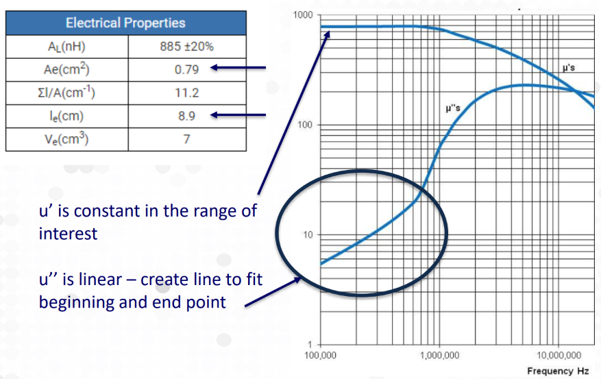
- From the manufacturer’s datasheet. For an ungapped core the impedance is
Z = jωN²·(Ae · μ · μ₀)/le, where μ\ is the frequency-dependent complex permeability, le the magnetic path length, Ae the core area, N the turns, and ω the angular frequency. ThenRp = 1 / Real(1/Z). Because the datasheet gives μ\* versus frequency, you can build Rp as a function of frequency directly. In the source example, μ′ was roughly constant over the range of interest while μ″ was fit linearly between the endpoints, and the resulting Rp rose with frequency.
Step 4: Solve for the Winding Resistance (Rw)
With Cw and Rp known, remove them from the measured impedance to leave Rw. Two forms:
- Full method. Define the magnetic branch impedance from L and Rp, then solve the full network for Rw. This is exact within the model.
- Simple method. Subtract the capacitive and Rp effects in the parallel space directly. This is only valid when Rw is small compared with the real part of the L–Rp parallel combination, but when that holds it is quicker.
A correct extraction gives a physical result: Rw increases with frequency, as skin and proximity effects raise the AC winding resistance.
A Worked Example: A 15-Turn Inductor, 100–500 kHz
The source presentation runs one device through the whole method: a 15-turn inductor on a Fair-Rite 5943002701 core, measured from 100 kHz to 500 kHz in 25 kHz steps on an HP4285A impedance analyzer. Rp was built from the manufacturer’s complex-permeability data (μ′ was essentially constant across the range, μ″ was fit as a line between the endpoints), which gives an Rp that rises with frequency. Cw came from the device’s SRF and low-frequency inductance, and Rm and Xm were read at each step with a short fixture (current-injection and voltage-measurement connections kept separate). Plugging those into the extraction returned a winding resistance that rose smoothly with frequency across the sweep: the physical result you want to see, and the confirmation that the Cw and Rp estimates were good enough to trust.

Step 5: Check for Non-Physical Results
Two error signatures tell you the extraction is wrong:
- Negative extracted resistance: the obvious error; a resistance can’t be negative.
- Resistance that trends downward with frequency: the subtle error. Winding resistance should rise with frequency, so a downward trend is non-physical and points to a measurement or parameter error (often a bad Cw or Rp estimate, or fixture strays).


Catching the subtle case is what separates a usable measurement from a misleading one, which is why the results always have to be interpreted, not just recorded.
Why It Matters
Knowing how much of an inductor’s loss is core versus winding tells you where to spend design effort: a core-loss-dominated part wants a different material or flux level, while a winding-loss-dominated part wants a different conductor or winding strategy. WCM’s measurement precision underpins this kind of work; the broader test capability is described in the WCM capabilities overview, and the winding-loss side of the problem is covered in litz wire design for high-frequency windings. When a measurement is genuinely hard to trust, WCM also models the component in finite element simulation.
This capability was presented at APEC 2019 by WCM engineers Weyman Lundquist and Mary E. Clark.
FAQ
Because an impedance analyzer measures the whole device at once. The reading includes the winding resistance, the core loss, the inductance, and the winding capacitance combined. To isolate the winding resistance you must first determine the winding capacitance and the core’s parallel loss resistance and remove their effects, and small errors in those two quantities can produce plausible but wrong loss numbers.
From the self-resonant frequency (SRF) and the low-frequency inductance, using Cw = 1 / (L·(2π·f_SRF)²). For instance, about 7 µH with a 13.8 MHz SRF gives roughly 19 pF. It is an approximation because both inductance and capacitance can vary with frequency and the inductance is measured at low frequency.
Two ways. Build a 1:1 transformer test device with the same turns, fine wire, and no gap, keep the windings far apart, and measure Rp on a four-terminal LCR meter at the frequency of interest. Or compute it from the manufacturer’s complex permeability: for an ungapped core Z = jωN²·(Ae·μ*·μ₀)/le, and Rp = 1/Real(1/Z), which gives Rp versus frequency.
Two non-physical signatures. An extracted resistance that is negative is the obvious error. An extracted resistance that trends downward with frequency is the subtle error, because winding resistance should rise with frequency as skin and proximity effects grow. Either result means a measurement or parameter error, often a bad capacitance or Rp estimate, or fixture stray impedance.
Not always measure. Before extracting, evaluate the device to decide whether extraction is useful; for some components a finite element simulation is both faster and more accurate than a bench extraction. The measurement approach is best when you need to validate a real part and can control the fixture and the Cw and Rp estimates well enough to trust the result.
 Measuring Core and Copper Loss in Magnetic Components
 Contact Us