What Is a High-Current Chassis-Mount Power Inductor, and When Do You Need One?
Published by West Coast Magnetics, July 2026, based on our 2024 company newsletter; content reviewed and confirmed current as of publication.
A chassis-mount power inductor is a high-current inductor designed to bolt directly to a chassis or enclosure, placing the component’s thermal mass in contact with the system’s structural metalwork. WCM’s 75 µH, 220 A chassis-mount power inductor pairs a patented foil winding with a high-Bsat core that keeps inductance stable at high peak current, delivering low AC loss and low DC resistance for boost-stage applications where both the current level and the ripple make conventional wire windings impractical.
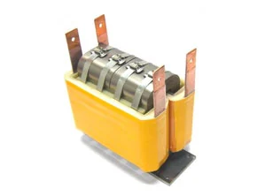
A chassis-mount power inductor is a power inductor packaged for direct mechanical attachment to a chassis or enclosure, typically with copper bus-bar terminals that carry high current directly to the board or bus. The chassis provides a thermal path for heat dissipation, which is why chassis mounting is preferred when current levels make PCB-mount thermal management inadequate.
A boost inductor is an energy-storage inductor placed in the input stage of a boost converter. It accepts current from the source, stores energy in its magnetic field, and releases that energy to step up the output voltage. Ripple current is the AC component of the current waveform superimposed on the DC operating current. At high power levels and switching frequencies in the kilohertz range, ripple current is a significant driver of winding loss: it requires low AC resistance in addition to low DC resistance.
What Is a Chassis-Mount Power Inductor, and Why Does the Package Matter?
Power inductors store energy in a magnetic field and release it to regulate current in power supplies and converters. In any switching converter, the inductor operates at the switching frequency, which means the winding sees both DC current and an AC ripple component. The winding loss from that ripple grows with frequency, which is why winding construction matters as much as inductance and current rating.
The chassis-mount package addresses a problem that PCB-mount parts cannot: thermal management at very high currents. At 220 A continuous, the winding’s DC resistance generates significant heat. Mounting the part directly to a chassis structure gives the inductor a thermal path that a PCB alone cannot provide. Copper bus-bar terminals carry current efficiently at these levels, and the chassis provides the heat sink.
At these current levels, the choice of core and winding technology is as important as the mounting arrangement. A high-Bsat core is required to avoid magnetic saturation at the peak current the inductor sees, which in a boost stage rises above the 220 A average. The winding must handle both the DC losses at 220 A and the AC losses from kilohertz-range ripple current without excessive temperature rise.
The WCM Chassis-Mount Power Inductor: Specifications
The WCM chassis-mount power inductor is a custom-engineered part built around an operating point that standard catalog inductors do not reach:
| Parameter | Value |
|---|---|
| Inductance | 75 µH |
| Rated current | 220 A continuous |
| Core | High saturation flux density; holds inductance through the peak currents of a boost stage (over 200 A) |
| Winding | Patented foil winding, low AC loss and low DC resistance |
| Switching frequency | 10 kHz (in the EV-bus wireless-charging application below) |
| Mounting | Chassis-mount, copper bus-bar terminals |
The combination of 75 µH and 220 A continuous puts this part in a performance band that standard product families do not reach. It is a custom design, engineered to a specific application’s electrical, thermal, and dimensional requirements.
For the product page, see the WCM chassis-mount power inductor.
The Application: Boost Inductor in a Zero-Emission Bus Wireless-Charging System
The WCM chassis-mount power inductor was designed and built for a specific application: the boost inductor in a wireless charging system for a zero-emission all-electric bus.
In that system, the inductor operates as the boost-stage energy storage element, managing the high ripple current at 10 kHz within a 100 kW wireless-charging system. That 100 kW is the charging system’s power throughput, the power flowing through the wireless charging link into the bus’s drive battery. The inductor is the 75 µH, 220 A part that handles that ripple at the system’s switching frequency; the 100 kW describes the charging application, not the part.
Zero-emission electric buses operate from large-format battery systems that require high-power charging infrastructure. Wireless charging (inductive power transfer) eliminates the mechanical connector and the wear and safety concerns that come with it, but it requires high-power, high-efficiency power electronics on both the ground-side transmitter and the vehicle-side receiver. The boost converter stage on the receiver side sees continuous high current with significant AC ripple at the charging frequency. That is the exact operating condition the WCM inductor was engineered for.
At 10 kHz and 220 A, the winding design is the engineering problem. A conventional solid-wire or standard foil winding at this current level and frequency would produce excessive AC winding losses from the ripple component. The solution is the patented foil winding described in the next section.
For the general design principles behind boost inductors in switch-mode converters, including core selection, ripple current, and duty cycle tradeoffs, see buck and boost inductors for SMPS converters.
Why Patented Foil Winding: Low AC Loss and Low DC Resistance at High Current
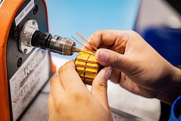
The winding technology in the WCM chassis-mount power inductor is the same patented foil winding used across WCM’s shaped-foil inductor families: a cutout foil design that combines low DC resistance with low AC resistance by reshaping the copper near the core gap.
In a standard foil winding, every foil turn is a solid conductor, and the gap fringing flux drives a strong proximity effect that pushes AC current into the conductor surface. The result is AC resistance that climbs steeply with frequency. At 10 kHz and high ripple current, that AC resistance penalty translates directly into winding loss and heat.
The patented foil winding removes copper near the core gap so the gap fringing flux equalizes current distribution across the winding cross-section. The result is single-layer behavior with very low proximity effect: the winding keeps foil’s low DC resistance and recovers the low AC resistance that full foil normally loses at high frequencies. At high-ripple, kilohertz-range operating conditions, this is the lowest-loss winding option for a gapped power inductor.
This technology was developed with Dartmouth’s Thayer School of Engineering (Professor Charles Sullivan and Dr. Jennifer Pollock). The patent covering the shaped/cutout foil winding is US20170221625A1. WCM is a licensee.
For the measured winding-loss comparison data (foil-cut versus full foil, litz, and solid wire), see low AC resistance foil-cut inductor. For the winding-loss principles and how shaped foil compares across conductor types, see minimizing winding losses in high-frequency inductors.
The high-Bsat core material is the other half of the design. A core that saturates below 200 A of peak current would allow inductance to collapse under transient load, which would defeat the converter’s current regulation. A high-Bsat core maintains permeability and inductance through the peak current events the boost stage can experience.
How to Specify a High-Current Custom Power Inductor
The WCM chassis-mount inductor illustrates the specification process for any high-current custom design: the operating point starts with inductance and current, but the real engineering problem is the combination of DC loss, AC ripple loss, peak saturation current, and thermal management at the package level.
The key parameters to define before specifying a high-current chassis-mount power inductor are:
- Nominal inductance and the acceptable tolerance band
- Continuous rated current (determines DC winding loss and thermal rise)
- Peak current (sets the core’s required Bsat margin above saturation onset)
- Switching frequency (determines AC ripple loss and winding technology selection)
- AC ripple magnitude (as a percentage of DC, drives winding loss at the operating frequency)
- Operating temperature range and thermal environment (chassis-mount assumes the chassis is a heat sink; define the contact conditions)
- Physical envelope and terminal type (copper bus-bar for high current; confirm bus-bar pitch and bolt pattern)
When those parameters are outside the range of WCM’s standard shaped-foil inductor families (which cover buck/boost applications up to 55 A continuous in the WCM317 through WCM320 series), a custom chassis-mount design is the path. WCM designs and manufactures custom inductors in-house, including the core, bobbin, and winding. The inductor does not depend on an off-the-shelf core or bobbin.
If you are evaluating whether a custom chassis-mount power inductor is the right direction for a high-current boost application, contact us with your requirements or browse the full power inductor line to see where standard parts leave off and custom engineering begins.
For compact shaped-foil inductor options at lower current levels, see the WCM317/318 saturation and selection guide.
When standard components do not fit your needs, our teams will engineer a solution.
FAQ
A chassis-mount power inductor is a high-current inductor designed to bolt directly to a chassis or equipment enclosure rather than mount to a PCB. The chassis provides a thermal path for heat dissipation, which is critical at current levels where PCB-mount thermal management is insufficient. Copper bus-bar terminals carry current directly to the system bus or board. Chassis mounting is the standard approach for power inductors rated above roughly 100 A continuous, where both the mechanical connection and the thermal path to a large heat-sinking structure are essential.
The WCM chassis-mount power inductor is a 75 µH, 220 A custom-engineered part with a patented foil winding and a high-Bsat core. It stores energy in its magnetic field and regulates current in a boost converter stage. The high-Bsat core maintains inductance through peak currents exceeding 200 A. The patented foil winding keeps AC winding loss low at the switching frequency while maintaining low DC resistance at 220 A continuous. It is produced as a custom part, engineered to the electrical, thermal, and dimensional requirements of the target application.
No. The 100 kW is the wireless-charging system’s power throughput, the charging power delivered to a zero-emission all-electric bus. The inductor is the 75 µH, 220 A part that manages the high ripple current at 10 kHz within that system’s boost converter stage. The 100 kW figure describes the charging application, not the component, and it is the system-level context that set the inductor’s electrical requirements.
At high current and kilohertz switching frequencies, the AC ripple component of the current creates winding losses that grow steeply with frequency in standard solid-wire and full-foil windings. In a gapped core inductor, the gap fringing field drives a strong proximity effect that pushes AC current to the conductor surface, raising AC resistance. The patented foil winding removes copper near the core gap so the fringing flux instead equalizes current distribution across the winding. The result is low AC resistance alongside low DC resistance, the combination that conventional wire and plain foil windings cannot achieve simultaneously. At 10 kHz with significant ripple current, the difference in winding loss is meaningful for both efficiency and thermal management.
The core must have a sufficiently high saturation flux density (Bsat) to remain above saturation at the application’s peak current. In a boost converter, peak current can significantly exceed the continuous rated current during transients. If the core saturates, its permeability drops, inductance collapses, and the converter’s current regulation fails. The WCM chassis-mount inductor’s core is selected for a Bsat high enough to handle over 200 A of peak current while maintaining inductance through those events.
Contact WCM when your application requires an inductance and current combination that standard catalog parts do not cover, typically when you need more than roughly 55 A continuous in a shaped-foil design, when you need chassis mounting with copper bus-bar terminals at very high current, or when the combination of inductance, Bsat margin, switching frequency, and thermal envelope requires a fully custom core and winding design. WCM engineers custom power inductors in-house, including the core, bobbin, and winding, without depending on off-the-shelf core geometries. Start with your inductance, rated current, peak current, switching frequency, ripple magnitude, and thermal environment, then contact us.
 Contact Us