EV Charger Transformer Design: How a Custom WCM Transformer Reached 98% Efficiency in a Level-2 Charger
Published by West Coast Magnetics, June 2026, based on our EV transformer comparison study (available for download below); content reviewed and confirmed current as of publication.
West Coast Magnetics, working with Kettering University’s Advanced Power Electronics Lab, replaced a non-functional planar transformer in a single-phase Level-2 EV battery charger and brought the charger to 7.2 kW at 98% efficiency. The planar transformer carried 3 nF of secondary-side winding capacitance that drove a high-frequency oscillation severe enough to keep the system from working. The custom WCM transformer suppressed that winding capacitance, eliminated the oscillation, and integrated the resonant inductor inside the transformer. The original program target was greater than 97% efficiency, a 3% gain over the 94% typical of existing chargers, and the WCM design exceeded it.
An EV charger transformer is the isolating, high-frequency power transformer in an onboard or off-board electric-vehicle battery charger. It transfers power from the AC line side to the DC battery side, provides galvanic isolation, and in resonant topologies also sets the resonant behavior that determines efficiency. In this design the transformer is the component that decided whether the charger worked at all.
The Charger: Single-Phase Level-2, 7.2 kW, GaN-Based
The collaboration set out to build a high-efficiency Level-2 charger for electric vehicles with a clear specification:
- Input voltage: single-phase 208 VAC
- Output voltage: 200 to 450 VDC
- Power rating: 7.2 kW
- Target efficiency: greater than 97% (a 3% improvement over the roughly 94% efficiency common in existing chargers)
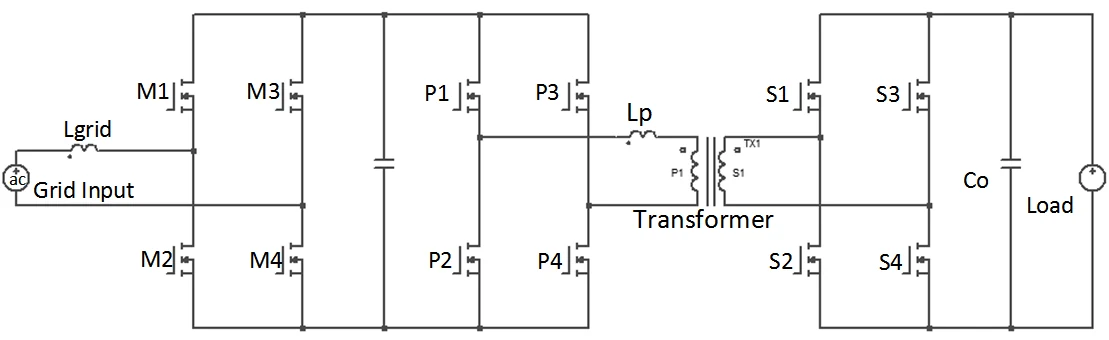
The selected topology uses GaN HEMTs from GaN Systems (devices P1 through P4 and S2 through S4) switching at frequencies up to 500 kHz. Pushing the switching frequency to 500 kHz shrinks the magnetics, but it also makes the transformer’s parasitics far more consequential: at that frequency, a few nanofarads of winding capacitance is no longer a second-order effect. That is the trap the planar transformer fell into.
Why Did the Planar Transformer Fail?
The planar transformer failed because 3 nF of capacitance measured across its secondary-side winding produced a high-frequency oscillation that made the system unable to work. This was not a marginal efficiency penalty. It was a functional failure.
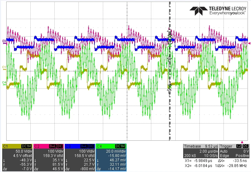
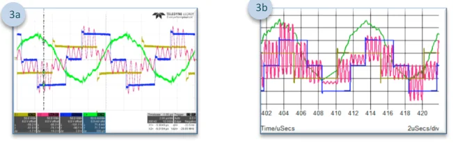
The planar unit measured 130 mm by 90 mm by 40 mm and required a stand-alone 10 µH inductor (Lp) placed outside the transformer to provide the resonant inductance. With the output set to 400 V, the measured secondary-side current (captured with a Rogowski coil) showed significant oscillation. The team confirmed the cause in simulation: once the 3 nF secondary winding capacitance was placed in the circuit model, the simulated current waveform matched the measured one exactly. The winding capacitance, not the surrounding circuit, was the source of the oscillation.
High switching speed makes this kind of parasitic the dominant design constraint. A planar transformer’s stacked PCB windings give it broad conductor-to-conductor overlap, and at 500 kHz that distributed capacitance resonates inside the power path. Controlling it is a winding-geometry problem, which is where a custom transformer design has room to act that a fixed planar part does not.
What the WCM Transformer Changed
WCM designed a custom transformer that did two things the planar part could not:
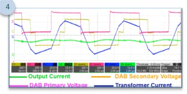
- Suppressed the winding capacitance. With the WCM transformer in the circuit, the high-frequency oscillation disappeared. The secondary-side current ran clean, with no oscillation visible in the waveform.
- Integrated the resonant inductor. The 10 µH inductor (Lp) that sat outside the planar transformer as a separate component was built inside the WCM transformer, saving board space and removing a part from the bill of materials.
Integrating the resonant inductance into the transformer is the same in-house custom power inductor and transformer design work WCM applies across its switch-mode magnetics: control the winding geometry to get the parasitics and the inductance you want, rather than bolting on discrete parts to compensate for a component that fights the circuit.
Planar vs. WCM Transformer: The Comparison
| Parameter | Planar transformer | Custom WCM transformer |
|---|---|---|
| Resonant inductor (Lp = 10 µH) | Stand-alone part placed outside the transformer | Integrated inside the transformer |
| Secondary winding capacitance | 3 nF measured | Suppressed |
| High-frequency oscillation | Present; made the system unable to work | Eliminated |
| Package size | 130 mm × 90 mm × 40 mm | Smaller (external inductor removed) |
| Charger result | Non-functional | 7.2 kW at 98% efficiency |
Comparison of the planar transformer and the custom WCM transformer in the same 7.2 kW Level-2 charger, per the WCM / Kettering University design study.
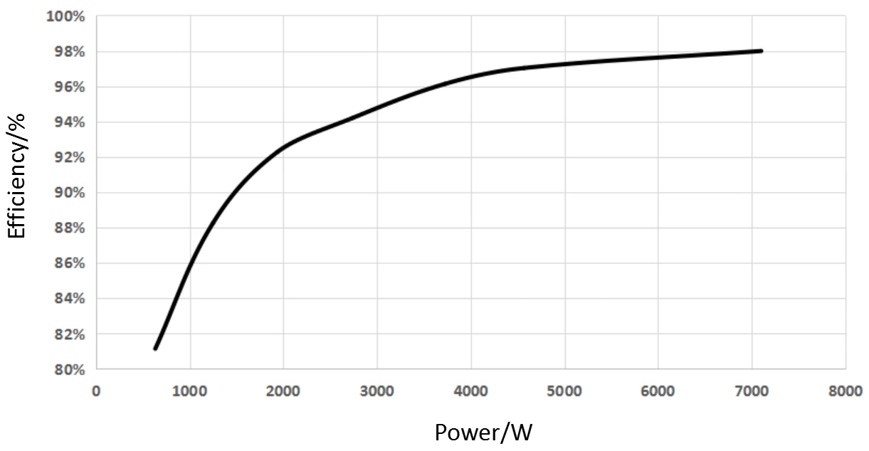
The Efficiency Result
With the oscillation gone and clean secondary current, the charger reached 7.2 kW at 98% efficiency. It is worth keeping two numbers distinct: greater than 97% was the program target, and 98% was the measured result. The 98% achieved figure clears the original target and represents roughly a 4-point gain over the 94% efficiency typical of the chargers the design was meant to improve on. The efficiency came from making the transformer work with the resonant topology instead of against it: the same custom magnetics expertise WCM brings to SMPS and switch-mode transformer design for medical, aerospace, and high-power industrial systems.
FAQ
The planar transformer had 3 nF of capacitance measured across its secondary-side winding. At switching frequencies up to 500 kHz, that winding capacitance produced a high-frequency oscillation severe enough that the system was unable to work. Simulation confirmed the cause: adding the 3 nF capacitance to the circuit model reproduced the measured oscillating current waveform exactly.
The charger reached 7.2 kW at 98% efficiency with the custom WCM transformer. The program target was greater than 97% efficiency (a 3% improvement over the roughly 94% common in existing chargers), so the 98% measured result exceeded the target.
It is a single-phase Level-2 EV battery charger: 208 VAC input, 200 to 450 VDC output, 7.2 kW power rating, using GaN HEMTs switching at frequencies up to 500 kHz. The efficiency target was greater than 97%.
The WCM transformer suppressed the secondary winding capacitance that caused the oscillation, and it integrated the 10 µH resonant inductor (Lp) inside the transformer. The planar transformer required that inductor as a separate stand-alone part placed outside it. Eliminating the oscillation and absorbing the external inductor let the charger function and saved board space.
As switching frequency rises toward 500 kHz, parasitic capacitance in the transformer windings has a far larger effect on circuit behavior. A few nanofarads that would be negligible at low frequency can resonate within the power path and dominate the current waveform. Controlling that capacitance through winding geometry becomes a primary design objective rather than an afterthought.
Yes. In this design WCM integrated the 10 µH resonant inductor (Lp) inside the transformer, removing the stand-alone external inductor the planar approach required. WCM designs its inductive components in-house, which is what makes it possible to fold the resonant inductance into the transformer winding rather than source and place a separate part.
 Contact Us